I'm the dude running this website. I am somewhere mid-life and spent 41 years of that
breaking things. I live in the Netherlands. I like coding, security, electronics,
motorbikes, tattoos, reverse engineering electronics and software. I get a kick out of
modifying things to make them do different things.
I also spent a fair amount of years supporting scam-baiters and clicking every link you
should avoid. As I got older more and more of my time goes into family and work, but late
at night I am generally knee-deep in code. I might as well own that I don't update this
blog very often. A handful of posts in 11 years speaks its own language.
Everything below up to 2025 was written on ihackshit.com between 2009 and 2025, and now
lives here. Anything newer than that was written here.
I wrote a tool to track down some odd hanging behavior I noticed lately on one of my many ThinkPads. The logs and journald tell me very little, because the writes hang mid-air in the freezes themselves — whatever would have explained the stall never makes it to disk before the machine comes back.
So it is a small Debian service in C that watches from the outside and keeps its own record, to find the thread that randomly hangs the laptop. Check out https://github.com/xecaz/hangwatch if you are interested.
While i am going rampant in my home, hacking anything with a display, the next logical move was a screensaver for my Sony Bravia KD-43X75WL tv. Check the write-up here: https://xecaz.com/Sony.Bravia.KD-43X75WL/
Every year I come back and make an empty post promising that I will try to maintain this blog better, and every year a new domain, more interesting projects spread across all these domains. This is another one of those posts ;)
Except in this one I am happy to announce I merged some of those domains into one, to make it easier to oversee everything I do. I moved ihackshit.com, ihackshit.nl and xecaz.nl all to xecaz.com where they always belonged, and repointed the domains to the new single source of truth.
While I was in there I fixed something embarrassing. The old site was loading full-size camera originals straight into 300 pixel boxes, so your browser downloaded a 2.8 MB photo to show you a thumbnail. One post from CCC Camp 2015 pulled 33 MB of pictures just to render eighteen of them. Everything now serves a proper thumbnail and only fetches the full resolution if you actually click a picture, which took the whole thing from 52 MB down to under 3. The originals are all still there, one click away, and they no longer carry the GPS coordinates they were quietly shipping with.
I hope this design is more readable as I got a lot of flak on hackernews for making my posts unreadable.
A few months ago I found the ESP32-DIV V2 on AliExpress and decided to get one. It is a nice little idea: an ESP32-S3 with a touchscreen, five buttons, a micro-SD slot, WS2812 LEDs, a CC1101 for sub-GHz, three NRF24 modules for 2.4 GHz, IR transmit and receive, BLE, and a battery. A pocket-sized wireless multitool for about the price of a takeaway.
Then I turned it on.
The battery didn't charge. A buzzer sat there beeping continuously. The SD card unmounted at random. Half the menu entries were work-in-progress placeholders. The on-screen keyboard was uppercase only — which means that if your wifi password contains a lowercase letter, and everyone's does, you simply cannot connect the device to a network. The buttons missed presses, double-fired, or lagged a full second behind my thumb. The battery indicator said 70%. It always said 70%.
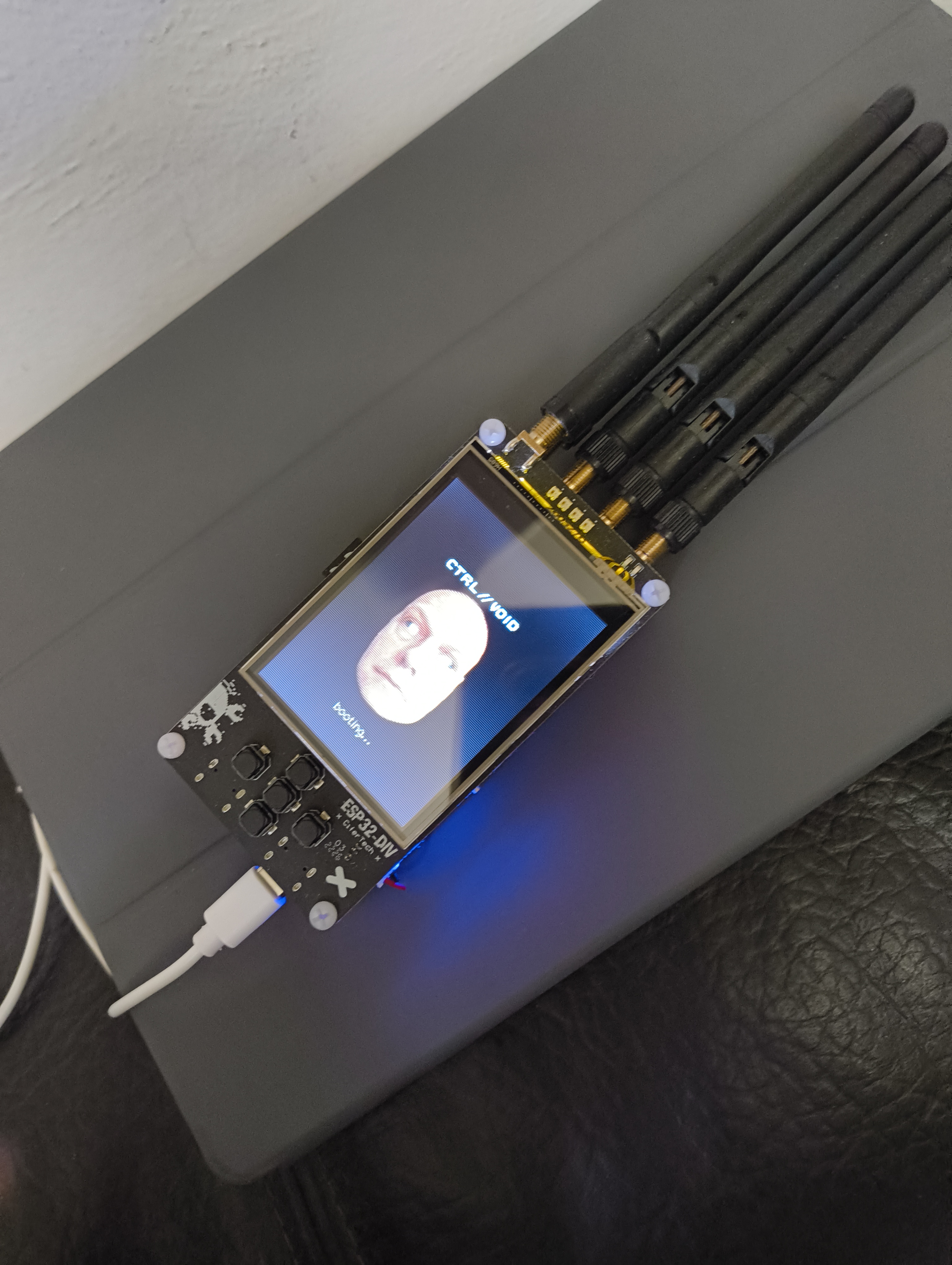
How it ended up: the replacement board booting CTRL//VOID.
It wasn't even their project
After digging a little I found out that this was just an open source project the seller had started manufacturing after finding it on GitHub. The hardware design, the firmware, the icons, all of it is CiferTech's ESP32-DIV. The seller had taken a hobby project that was honestly labelled as a work in progress, put it on a production line, and sold it as a finished product.
So I started bitching with the seller about shipping something this broken. They initially questioned my knowledge and asked if I was an electrical engineer. I explained that I wasn't, but that I could write them a better firmware.
Which, in hindsight, is the kind of thing you say and then have to go and do.
What was actually wrong
I pulled the stock firmware apart. It's around 20 kloc of Arduino sketch spread over ten files, and almost every symptom on my list traces back to one architectural decision: every feature is a while (!feature_exit_requested) { ... } loop that hijacks loop() and never gives it back.
Nothing else can run while a feature is running. Input is read by a bare PCF8574 poll with no debounce, no edge detection, and a hard delay(200) after every handled press. That's your laggy, missing, double-firing buttons: the input path is being starved by whatever feature owns the CPU, and when it does get a look in, a 200 ms sleep eats the next press.
The keyboard was even better. wifi.cpp declares keyboardLayout[]twice — lowercase at line 2197, uppercase at line 3948 — same symbol, so the linker just picks the last one and the lowercase layout silently vanishes. There is no shift, no layer switch, and the space key is dropped on the floor in KeyboardUI.cpp. Nobody ever tried to type a real password on it, because if they had, they'd have found this in thirty seconds.
That's when I stopped trying to patch it. You cannot bolt a USB stack, or a responsive UI, or anything that has to keep running in the background, onto a design where one feature owns the processor. The scaffolding had to go.
Starting over
I moved the whole thing to PlatformIO with ESP-IDF and Arduino as a component, so I could keep the useful Arduino radio libraries (TFT_eSPI, RF24, ELECHOUSE_CC1101, IRremote, NimBLE) while still reaching IDF-only things like the TinyUSB composite stack. Then I rebuilt the scaffold as FreeRTOS tasks: an input task on core 1 polling every 2 ms with proper per-key debounce, a UI task on core 0, radio workers, storage, and an I²C poller of its own. The UI became a screen stack with onEnter / onEvent / onTick / onRender / onExit, and the radio features became screens that plug into it instead of black holes that swallow the CPU.
The protocol logic in the original firmware is fine, by the way. The 802.11 raw-frame injection, the CC1101 register values, the NRF24 BLE hop tables — that's off-the-shelf glue and it works. It was never the radios. It was everything around them.
It ended up at about 14.6 kloc across 110 files, with 34 screens. Somewhere in there I named it CTRL//VOID.
The I²C rabbit hole, or: how to kill a board
With the architecture fixed the device felt like a different machine, but the buttons were still not right. Reads from the PCF8574 came back as garbage — occasionally as "all five keys pressed at once" — and every so often the bus would just stall for a full second.
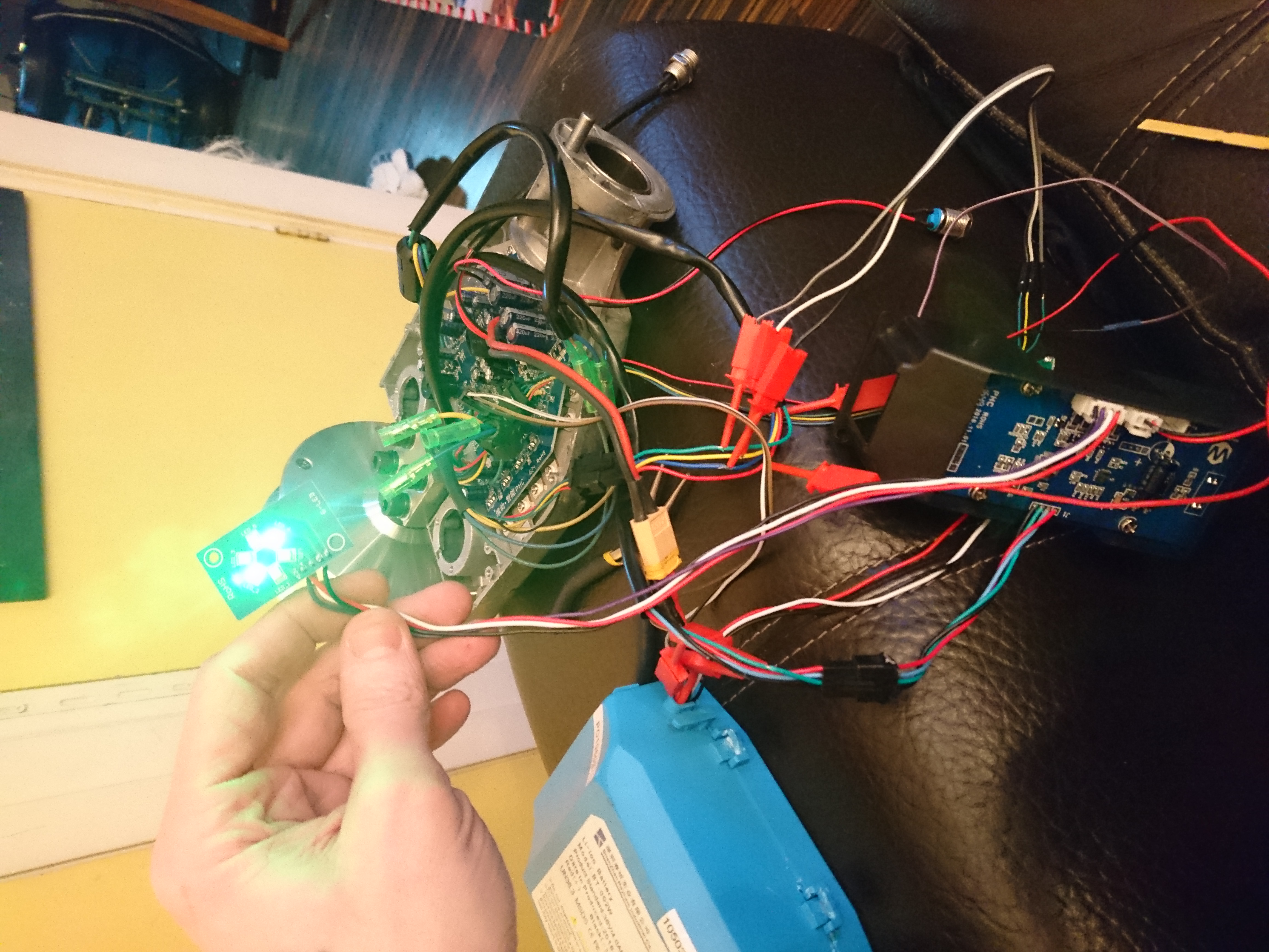
So I went down the hole. Dropped the bus to 50 kHz, which helped and shouldn't have needed to. Added a popcount glitch filter to throw away impossible reads. Added a manual bus recovery path: reset the peripheral, pulse SCL nine times, send a STOP. Then I got the soldering iron out and started moving things: SDA and SCL off the stock GPIO 8/9 and onto 41/42, the PCF interrupt line bodged onto GPIO 2. Each round of this meant desoldering, rerouting, reflashing, retesting.
On the fifth or sixth pass I killed it.
A free board
I'd stayed in contact with the seller through all of this, and somewhere along the way the tone had changed completely — they'd gone from asking whether I was qualified to following the work. When I told them I was done because I'd destroyed the device, they offered to send me a new one, free, so I could keep going.
That has never happened to me before. Say what you like about AliExpress sellers.
Two resistors
The new board arrived and I resumed. And within a day of having working hardware in front of me, the whole I²C saga collapsed into a single, slightly humiliating fact.
I went back to the schematic properly. R30 and R31 are the I²C bus pull-ups: 1 kΩ each, from 3V3 to SCL and SDA. My original board did not have them as designed. That's it. That's the whole thing. Every symptom — the garbage reads, the stalls, needing to crawl at 50 kHz, the glitch filter, the recovery path, the bodge wires, the resistors I'd swapped in by hand that got me most of the way there but never all of it — all of it was me writing software to work around two missing passives.
I asked the manufacturer. They confirmed the replacement board "now has the original 1k R30/R31". So the board I'd been fighting for weeks was, in the most literal sense, not built to its own schematic.
I tore out the workarounds. Stock GPIO 8/9, 400 kHz, no bodge wires, no recovery path, no speed derating. The glitch filter stayed because it costs nothing. The bus has been clean ever since.
A decent chunk of two months' work went in the bin that afternoon. I'd rather that than ship the workarounds.
The 70% battery
The permanent "70%" turned out to be the fallback value the stock firmware falls back to when it can't talk to the IP5306 — which, on a bus with no pull-ups, was always. But even working, that chip only reports charge in 25% buckets, which is not a battery gauge, it's a rumour.
There's a proper voltage divider on the board: R11 and R16, 100k each, putting VBAT/2 on GPIO 2. So I read that instead, on ADC1 so it keeps working with wifi up, and run it through a LiPo discharge curve.
The divider is a clean ÷2, but the pin reads a stable ~3.2× low — 651 mV where the tap should be around 2060 mV with the cell metered at 4.17 V. Rock steady, not settling noise, so something on GPIO 2 is loading it. It's linear, though, so one scale factor calibrates the entire range. 6.40, trimmable live on the diagnostics screen and saved to NVS, reads dead-on against a multimeter.
One thing I couldn't solve: you cannot detect whether a battery is present. With no cell fitted, the IP5306 floats VBAT to about 4.12 V — indistinguishable from a charged battery at 4.17 V. So the gauge always shows. I'd rather say that out loud than pretend.
Everything else
The rest is the long tail of things that were broken, missing, or marked "work in progress":
Keyboard. Four layouts — lower, upper, numeric, symbols — with shift, a working space bar, backspace, enter, arrow-key navigation alongside touch, and a password-mask toggle. You can type your wifi password now. Revolutionary.
Wifi. Scan, packet monitor, deauth, beacon spam, captive portal. The packet monitor was writing PCAP files containing nothing but the 24-byte header, because esp_wifi_init(nullptr) never set up promiscuous mode properly. Fixed, plus NTP sync so capture filenames carry a real timestamp instead of whatever the clock felt like. The deauth path was failing with 0x102 out of esp_wifi_set_mac — the MAC has to be set before the AP starts.
Captive portal. Serves its pages off the SD card rather than from strings baked into the C++, so you can edit them without a compiler. Configurable AP name. Captured credentials get appended to the card under /captures/portal and there's a scrollable list of them on the device.
USB. This one didn't exist at all before. TinyUSB composite: mass storage (the SD card shows up as a drive), a CDC serial console, and an HID keyboard. Which means Rubber Ducky over wired USB, arming on the device and firing when a host plugs in, with scripts read off the card.
USB modes. Standalone is the normal device. Appliance is a HackRF-style boot path with no menu at all, just a status card, where holding SELECT for three seconds gets you back. Bridge is scaffolding for driving the radios from a host.
Radios. Everything the stock firmware had, plus a 17-preset BLE spoofer, saved profiles for CC1101 and IR, and a fix for the sub-GHz replay running 2-FSK when it should have been OOK. The NRF24 spectrum sweep splits across the modules and comes out about three times faster.
LEDs. The board has four WS2812s. The stock firmware never drove them. They now signal RX and TX per radio, with per-channel colours you can edit.
The small stuff. Touch calibration with five points and automatic axis-swap and invert detection. Four themes. SD hot-plug with backoff instead of a one-shot mount at boot. Settings in NVS with schema versioning, so an update can retroactively patch in new defaults, and sanity clamps so a corrupt value can't brick the UI. Bad wifi credentials no longer hang the boot at the splash screen. A file browser. A diagnostics screen showing live bus health and battery millivolts.
One last thing I had to check
Late on, the seller's own firmware blobs landed in my lap and I had an uncomfortable thought: had they taken my work? So I pulled both binaries apart to find out.
They hadn't. It's the public upstream CiferTech firmware, v1.5.6, built as a flat Arduino sketch on someone's Windows machine — the build paths are still in the binary, along with a "Made By Cirket" signature. Of the 672 source string literals in my firmware, 26 appear in theirs, and all 26 are generic: keyboard layouts, MIME types, the captive-portal probe URLs every OS uses. Not one of my distinctive identifiers is in there.
Worth knowing which way round the story goes before you accuse anyone of anything. Theirs is also feature-stripped compared to upstream: it navigates by touchscreen hit-testing only, with no button bus at all, which sidesteps the I²C problem rather than solving it.
Get it
The firmware, the source, and a flashing guide are on GitHub: github.com/xecaz/ESP32-DIV. There's a prebuilt merged image so you don't need to install a toolchain — the easiest route is Espressif's web flasher in Chrome or Edge, flashing at offset 0x0. Or from a terminal:
One gotcha: while CTRL//VOID is running it takes over the USB port as a composite device, so flashers usually can't auto-reset it. Put the board into download mode by hand first — hold BOOT, tap RESET, release BOOT. Harmless to do even when it isn't needed. I got the CDC console to trigger a reboot into the bootloader, but the handoff from the OTG port to the ROM's USB stack isn't seamless and the port vanishes mid-handshake, so the button combo stays.
On the AI question
I might as well be straight about it: I did this with Claude. I fed it the schematic and the original firmware, described what the device was doing wrong, and had the bones of a new FreeRTOS firmware inside a few hours. It's also what pushed me to look at the I²C bus in the first place.
It was not a magic wand. It sent me down the bodge-wire path for weeks before we found the two missing resistors, and I'm the one who killed a board following that advice. But being able to iterate on 14 kloc of embedded C++ at that pace, on a device I'd never touched before, is not a thing I could have done on my own on evenings after work.
Anyway. If you own one of these and you're as disappointed with it as I was, try mine instead. The battery charges now.
I haven't stopped hacking, I have just been too annoyed with wordpress and it's vulnerabilities, the constant patching to keep updating my site. A while back I started thinking of dropping wordpress after a load of my own exploits were aimed at wordpress sites. It however took forever for me to get my thumb out of my ass to get cracking, but as you might see it happened now..
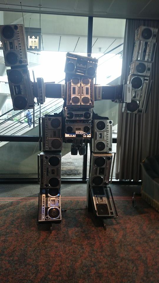
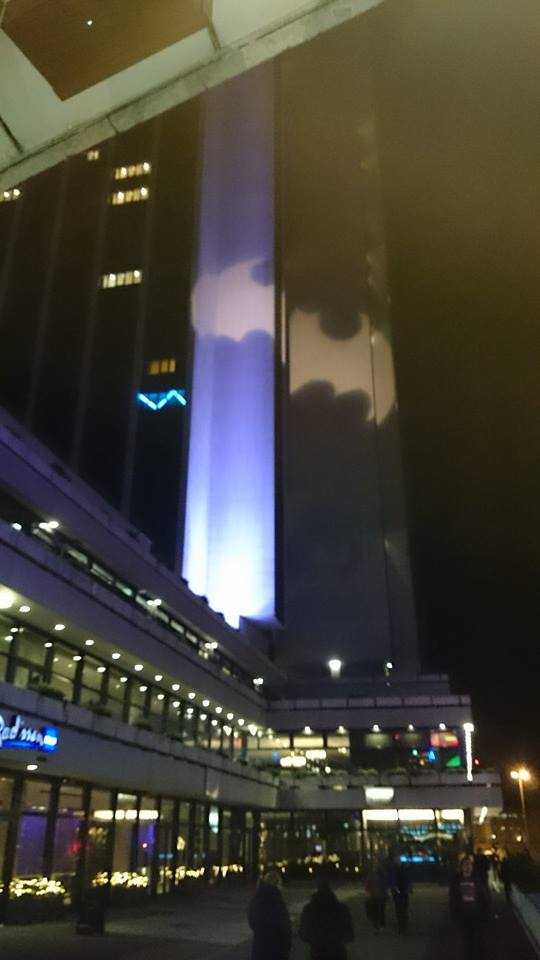
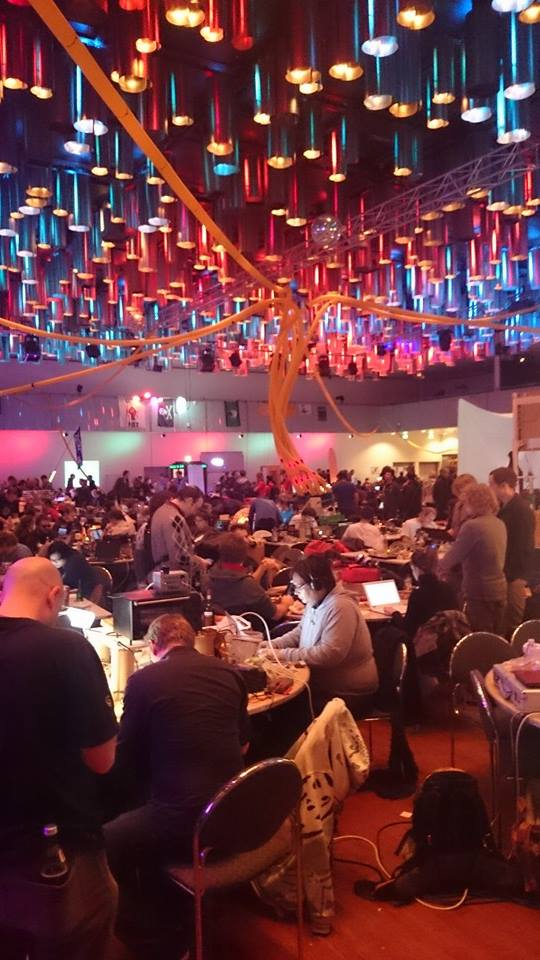
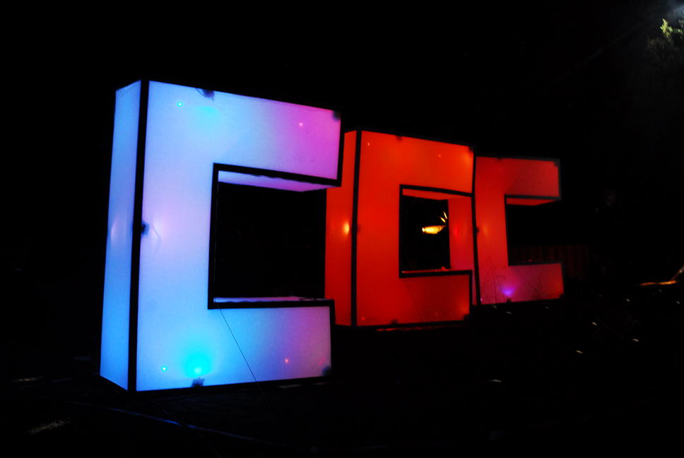
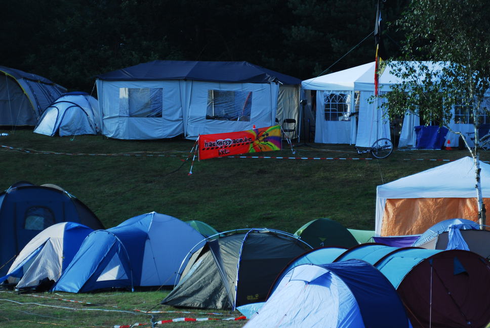
Other than this 2023 we spent at CCC camp outside of Berlin. Both these hacker camps deserves their own posts, so I will do that as I finish up migrating this site here but saying this I realize I have not shared anything from any of the other events I attended and shared what was achieved there either, so some placeholders are in place, expect more to come.
Me and my kiddo (now 8) just got back from WHY2025 and as usual the orga hit this one out of the park. Check out this flyover captured by stuckinstatespace on Youtube
King of the sidewalk - Pimping Chris Ride-on car Part 2 Quite some time has passed since my last real posts, and looking at the car it feels like not much has happened, but re-reading the blog I realized quite a lot did.
No, the massive motor, differential and chain-drive is not in place yet and as you could see in my last blog one of the old gearboxes died. I also mentioned I wanted to keep it rolling during the weekends when my little guy was here, so tearing it all down and start building the drive-chain on the car itself was a no-go for me.
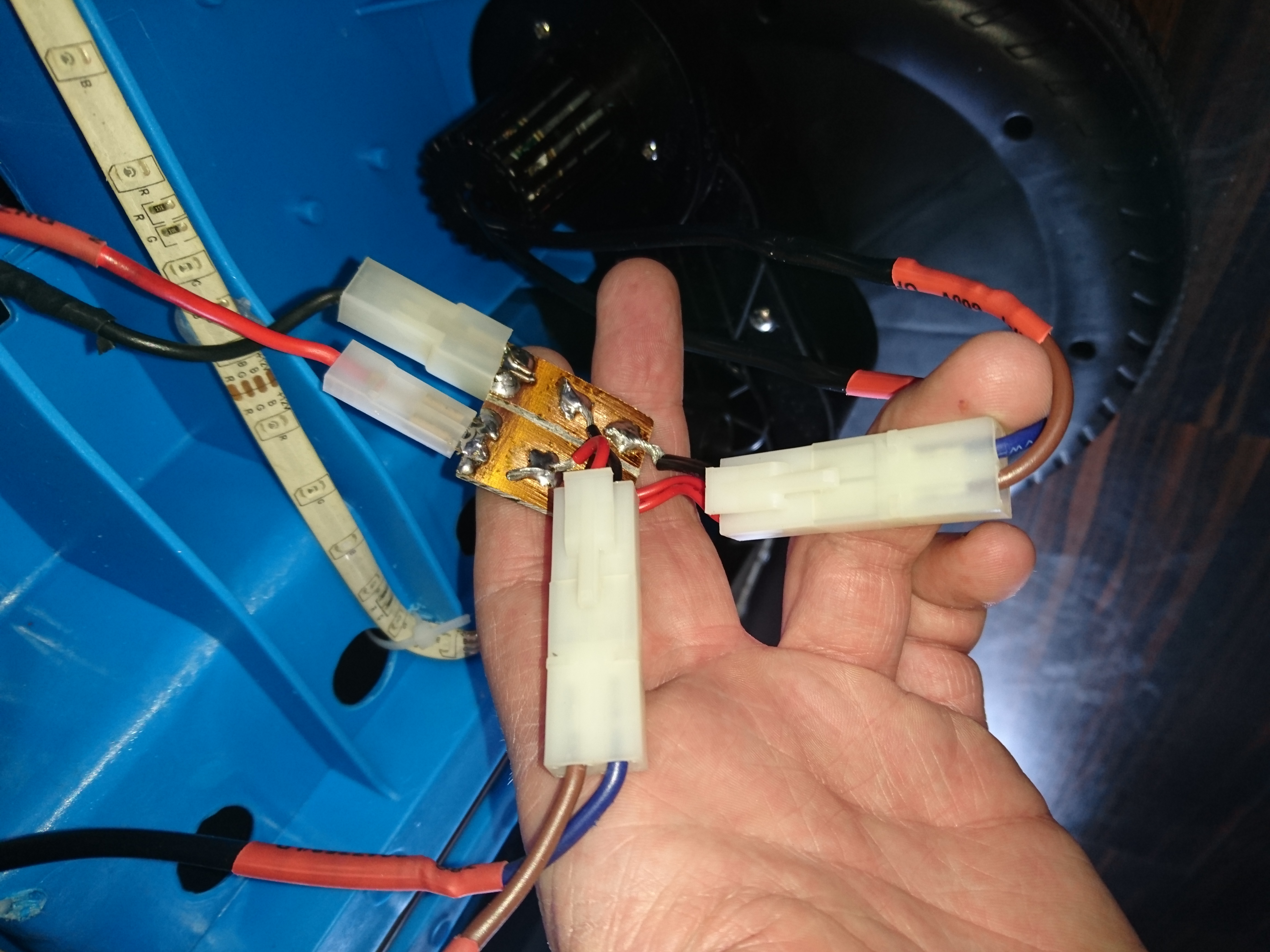
The cat ate the led-lights And what's left of it was pulled away by my soon to be 2 years old little rebel :) They will be replaced with more rugged LED strips for actual cars to make sure they get to stay.
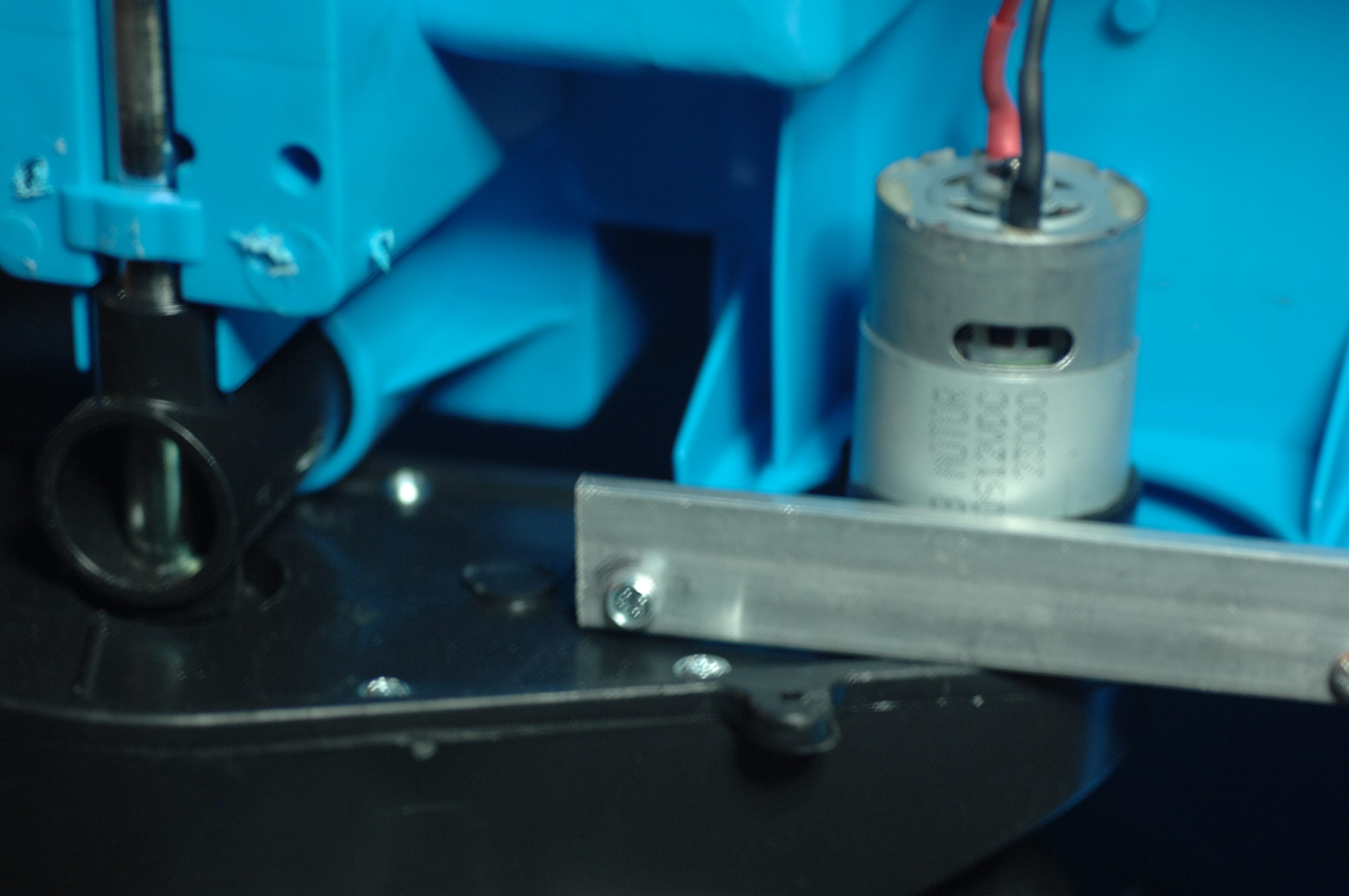
I made a few poor attempts to patch the old gearboxes, but ended up removing it all together while awaiting the somewhat beefier replacement 550's.
These are the RS-550 12VDC doing 23.000 rpm.
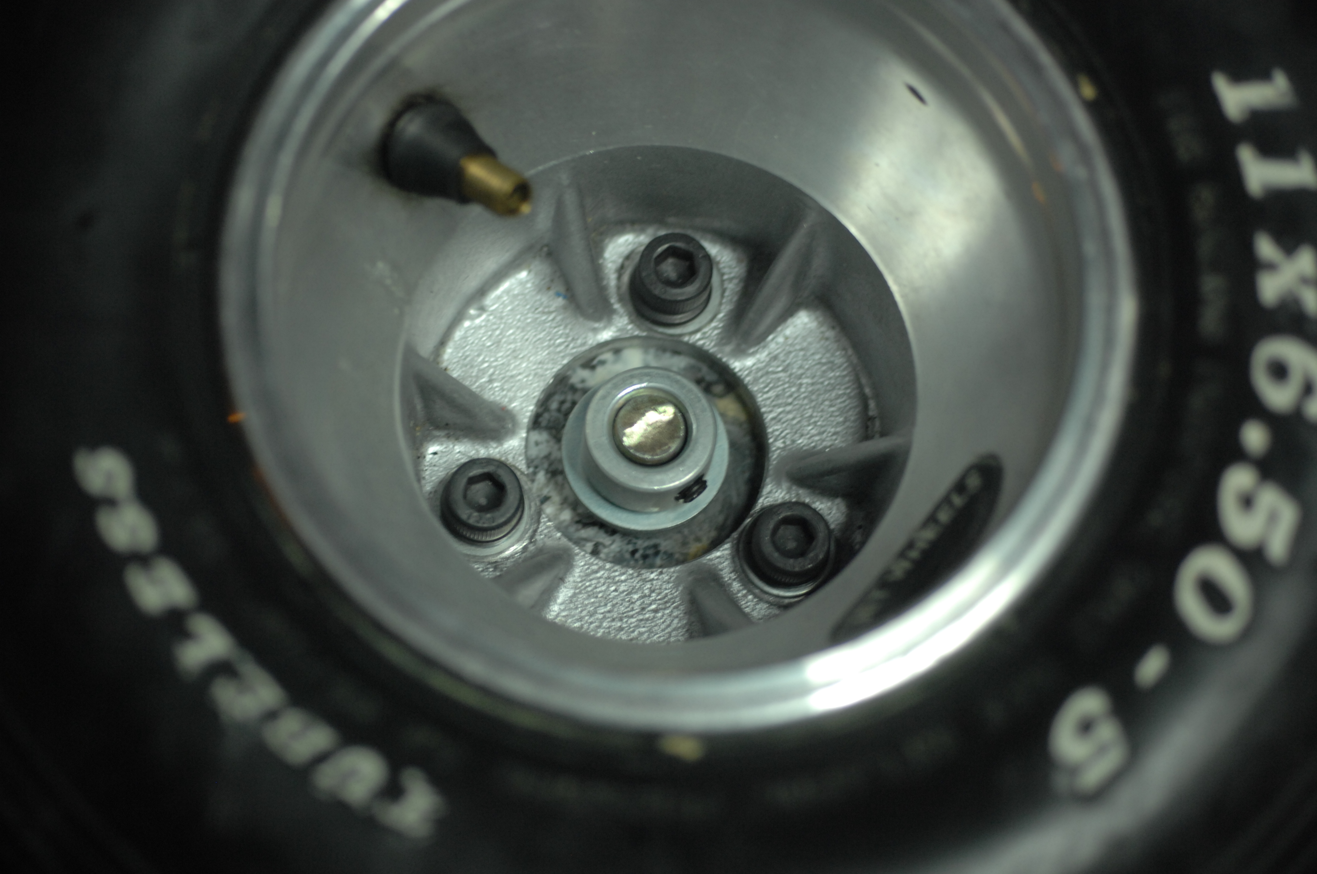
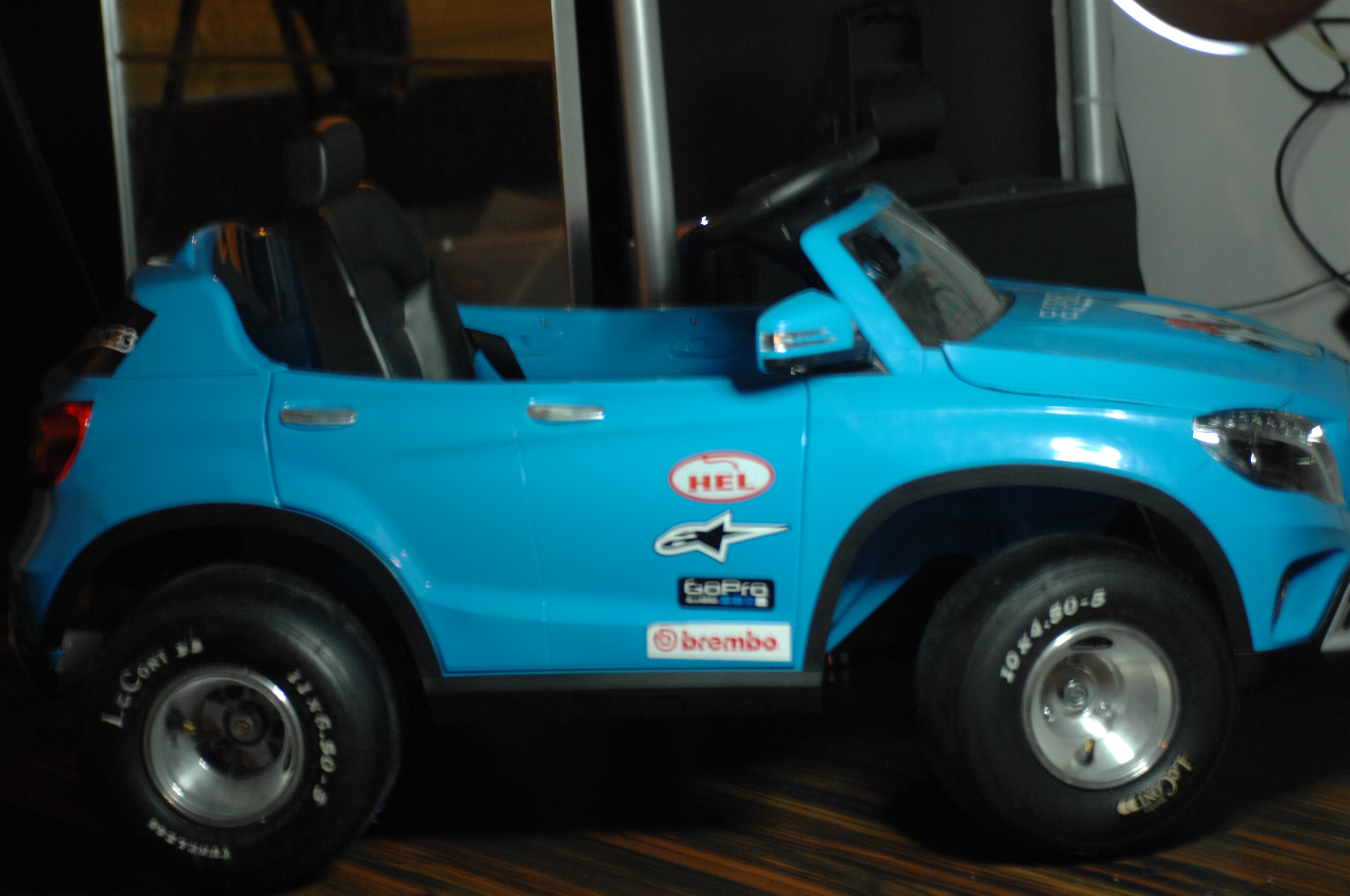
The search for wheels end Wheels were an issue, and yes, I went the expensive way with a set of used LeCont gocart tyres.
Front: LeCont 10×4.50-5.
Rear: LeCont 11×6.50-5.
I ended up paying around 160 euros for the set. It looks pretty fancy, I must say and my son loves them.
There is no object so soft but it makes a hub for the wheeled universe. Walt Whitman
I now had wheels but no hubs for the rims to go on and while browsing ebay I didn't find anything that was reasonably cheap or would just take too long to ship.
Being a responsible adult as I am, I have saved all scrap PLA from failed 3dprints, recycling this makes great sense. I decided to mold them so I measuring the inner diameter of the rim, then ran off to the local food-store and bought two canisters of corn that had just about the same diameter. The cans were emptied, cleaned and put on a the stow in a pan, heated to 210 degrees and the plastic was slowly added to make sure no large bubbles formed.
These chunks were milled flat to size. I drilled and tapped M8 holes and secured the wheel.
Art consists of limitation. The most beautiful part of every picture is the frame. Gilbert K Chesterton
I also started building the frame that once finished will replace much of the under-carriage of the current car. The game-plan is simple. Build a rolling frame with suspension, brakes, gears, differential, steering and motor and once ready transplant that frame to the car. Until now I started created 3 revisions of the back-end but stopped half way and reflected over decisions, scrapped it and started over again. This is most likely nothing what it will look like when "done".
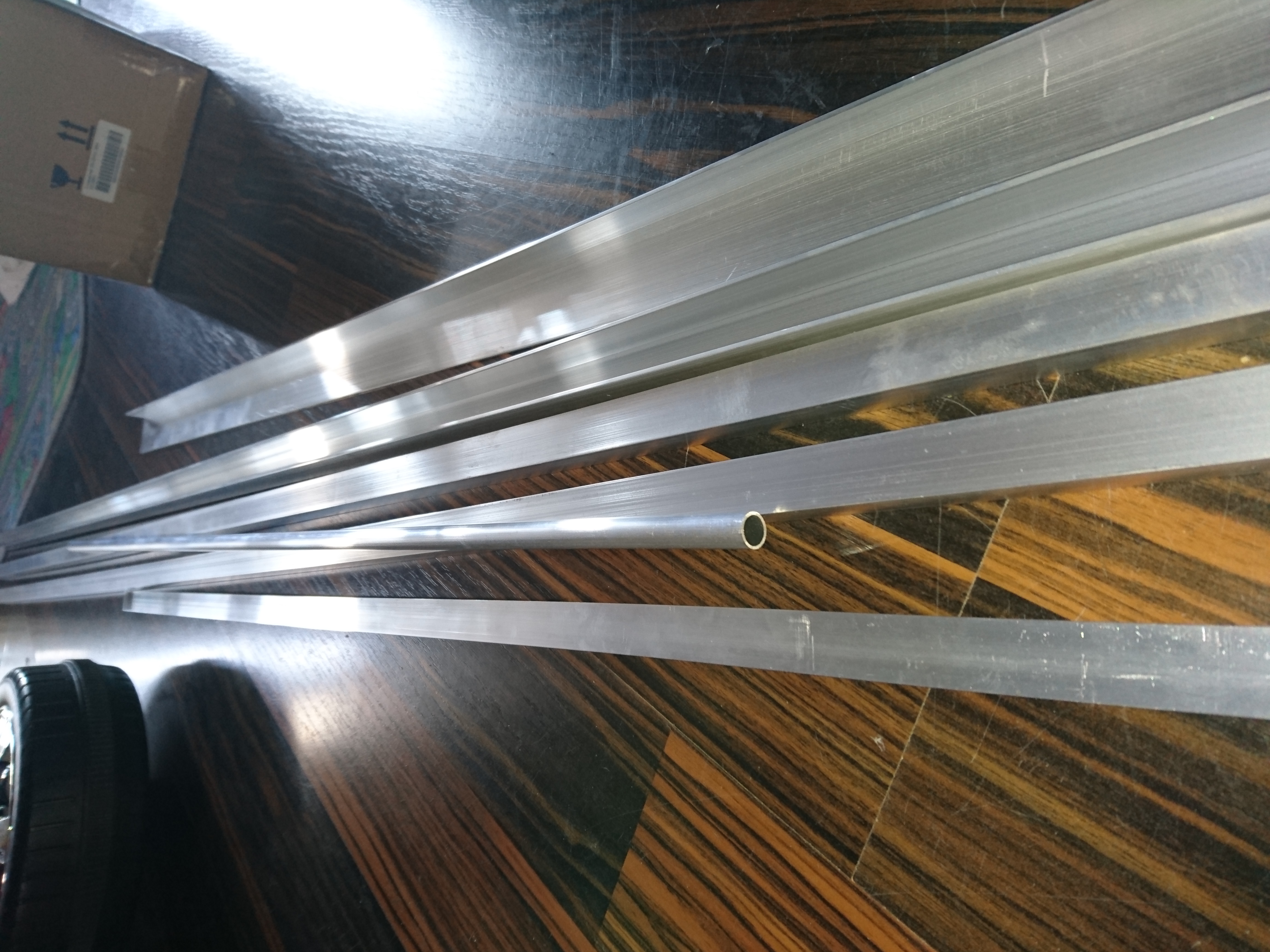
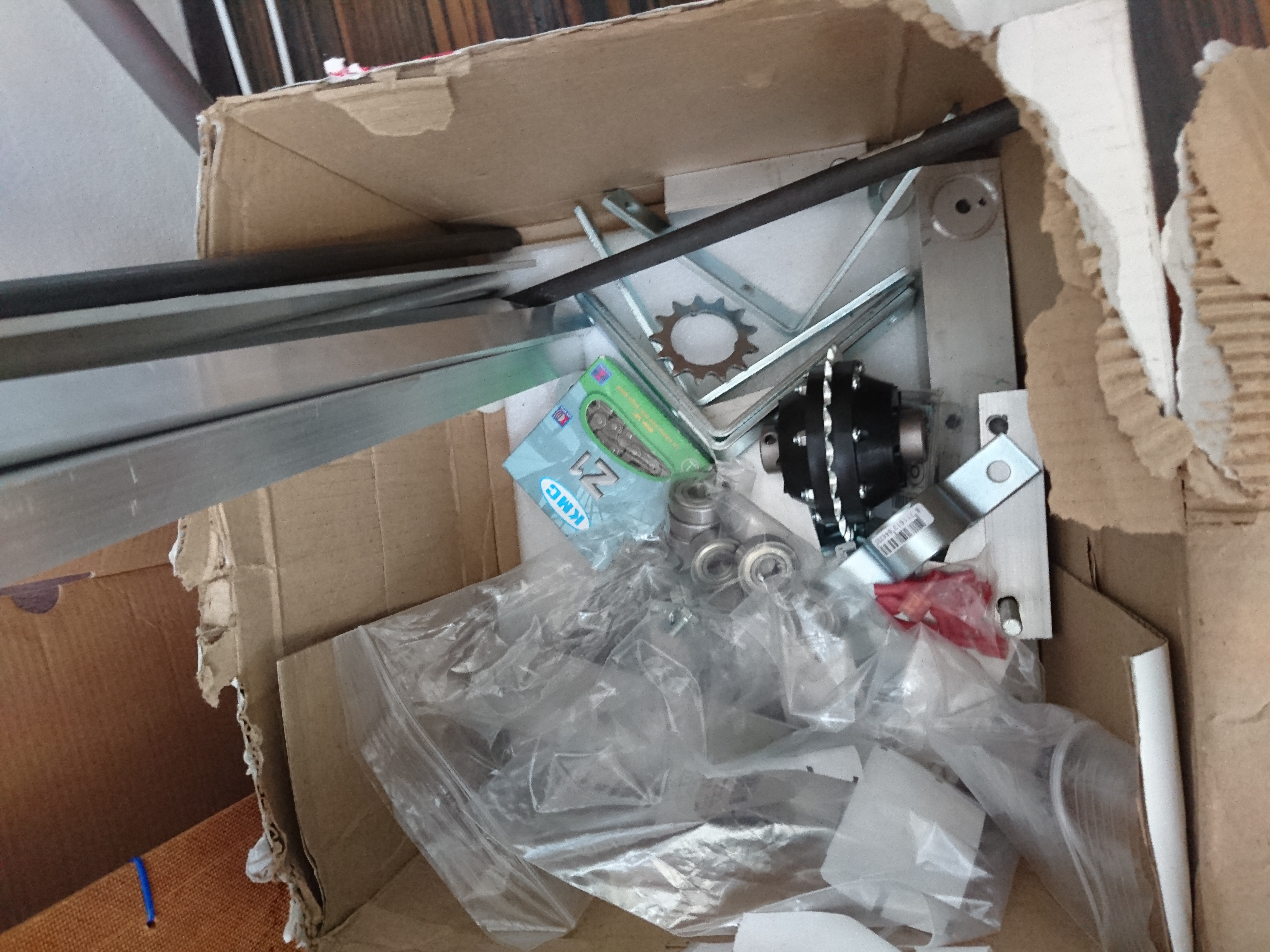
I have used aluminium as much as possible to keep the weight down. I got my hands on a 1300x60x40mm u-profile that shapes the base of the frame. The bearing housing holding the differential had to be milled down slightly, and 10x15mm strips add supports.
Initially flaky lower control arms moved me from cheap hollow tube, to solid square stock, to end up with 10mm thick aluminum blocks at the end.
I have been able to do most of the milling on my tiny Proxxon MF70 Micro-mill, but I REALLY need a bigger machine that eats more material, preferably CNC but for now this will have to do.
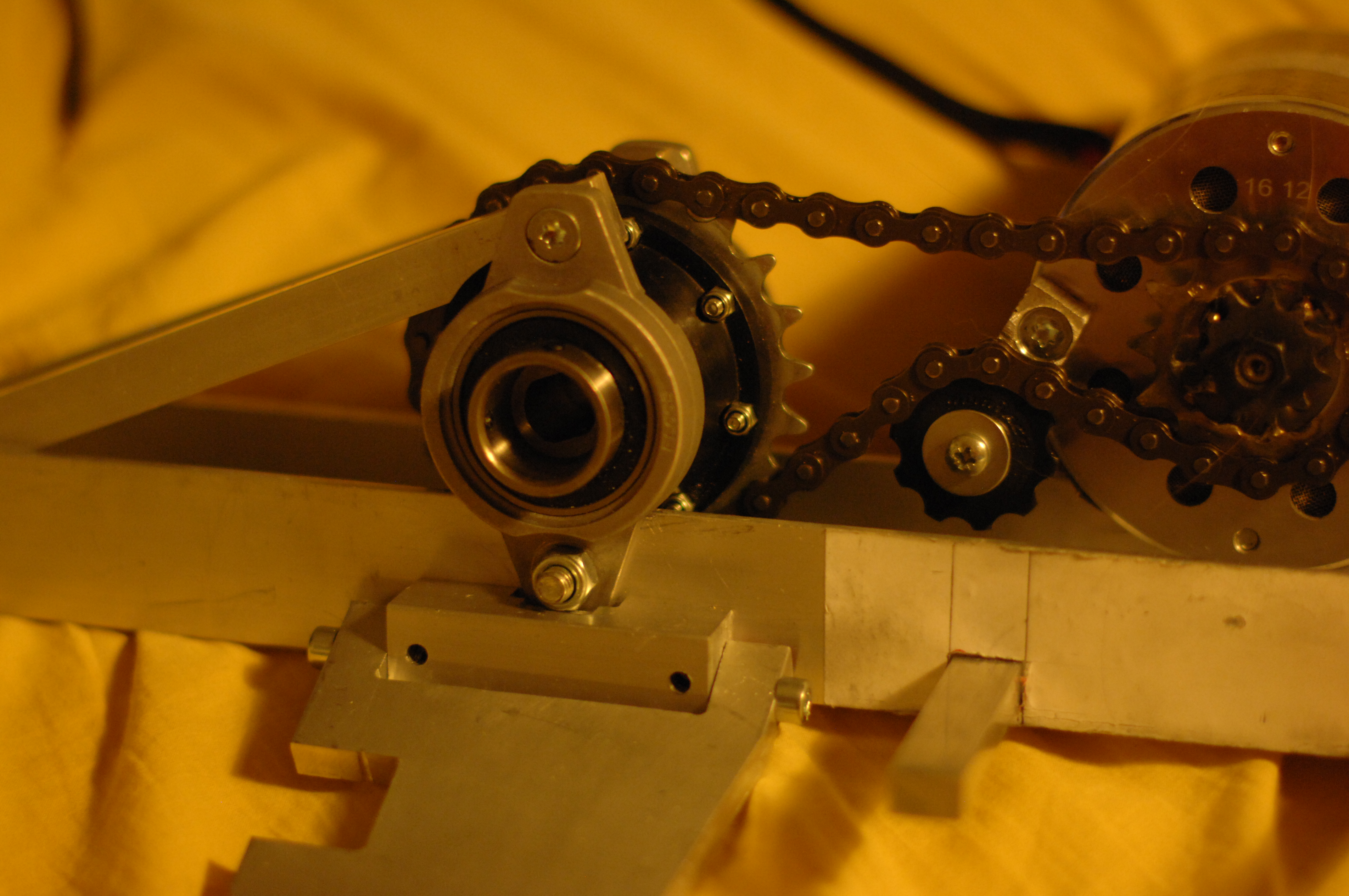
Rear differential, bearings, chain, chain-tensioner, electric motor and the lower control arm mounted. Battery box will be mounted on the opposite side to the motor to balance out the weight.
All of this will be covered under the driver seat to avoid anyone losing a tiny finger. I am considering to add linear actuators to the suspension to be able to raise and lower it as I think it would make it look sleeker. Not sure yet, leave your comments.
The child supplies the power but the parents have to do the steering. Benjamin Spock
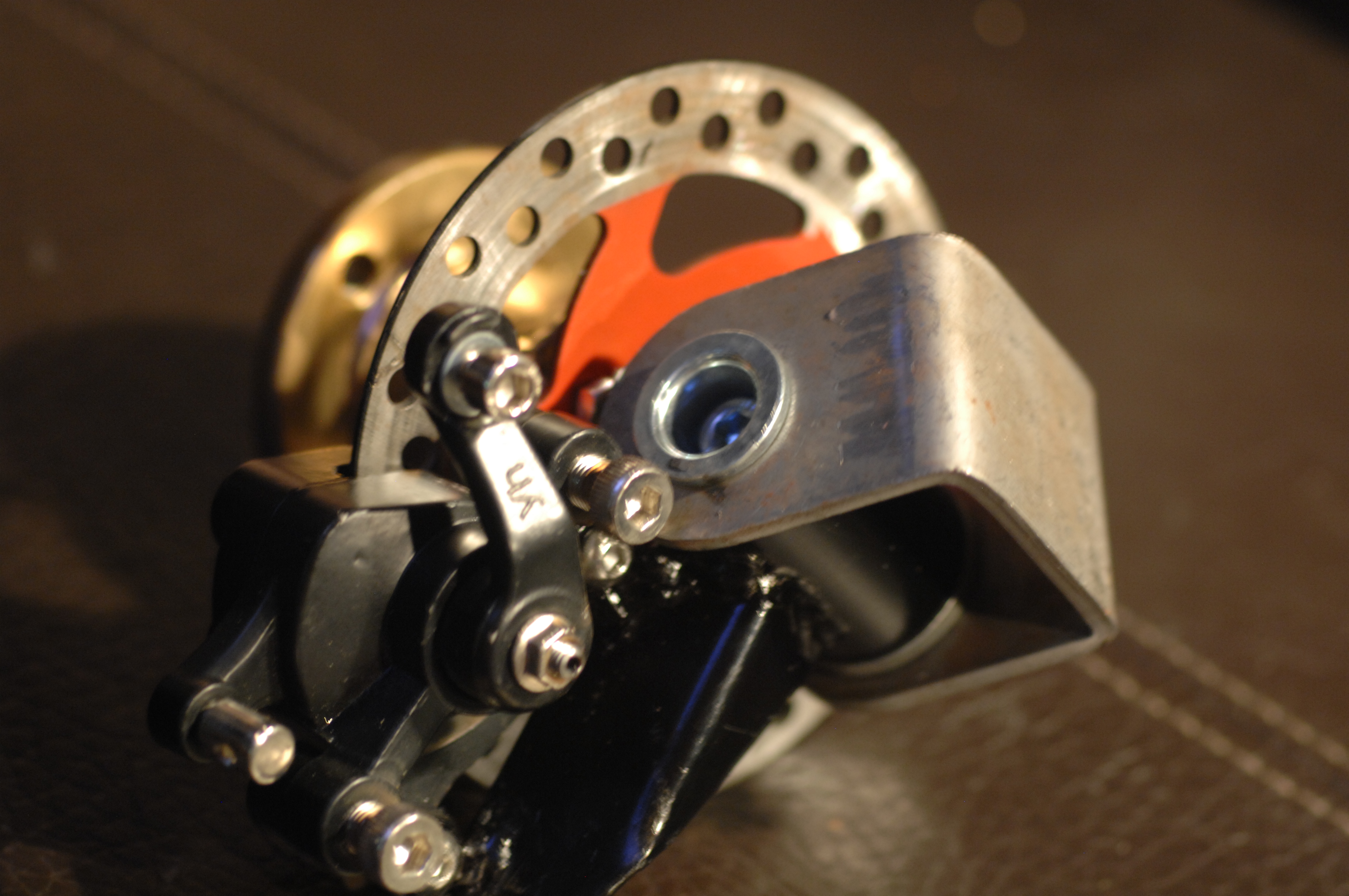
I bought a gokart front steering kit, including wheel-hubs. I welded a few nuts and bolts to them allowing the pocket-bike disc-brakes and calipers to be mounted, then gave them a splash of paint.
Life is made of ever so many partings welded together. Charles Dickens
I ended up buying a dirt-cheap 200 amp MMA/TIG. I burned a few boxes of rods and I am starting to get the feel of it. And yes, I even welded aluminium, but like everyone said, it's hard to do with stick (however not impossible).
So far this project is moving a lot slower than I wished for but it's busy days and I have spent a fair amount of time picking up milling, using lathe and welding. With this mix of new trades I am reconsidering a lot of decisions made prior to posting here, so you have not seen half of it.
Anyway, just wanted to let you know I was making some progress.
for CPU in $(ls /sys/devices/system/cpu/ |grep -E '(cpu[0-9])')
do
        CPU_DIR="/sys/devices/system/cpu/${CPU}"
        echo "Found cpu: \"${CPU_DIR}\" ..."
        CPU_STATE_FILE="${CPU_DIR}/online"
        if [ -f "${CPU_STATE_FILE}" ]; then
                STATE=$(cat "${CPU_STATE_FILE}" | grep 1)
                if [ "${STATE}" == "1" ]; then
                        echo -e "\t${CPU} already online"
                else
                         echo -e "\t${CPU} is new cpu, onlining cpu ..."
                         echo 1 > "${CPU_STATE_FILE}"
                fi
        else
                echo -e "\t${CPU} already configured prior to hot-add"
        fi
done
Hot-add RAM:
for RAM in $(grep line /sys/devices/system/memory/*/state)
do
        echo "Found ram: ${RAM} ..."
        if [[ "${RAM}" == *":offline" ]]; then
                echo "Bringing online"
                echo $RAM | sed "s/:offline$//"|sed "s/^/echo online > /"|source /dev/stdin
        else
                echo "Already online"
        fi
done
King of the sidewalk - Pimping Chris Ride-on car Part 1
As I promised a lot of the future posts will be about hacking toys.
In November I bought this Mercedes GLA Class Ride-on kids car for my 1 year old son, a car he loves so much but I have a feeling he will never love less as this build progresses.
You can find it at amazon
So some facts about the car:
Its about 120 cm long, 60 cm wide, 50 cm high and weighs in at around 25 kilos.
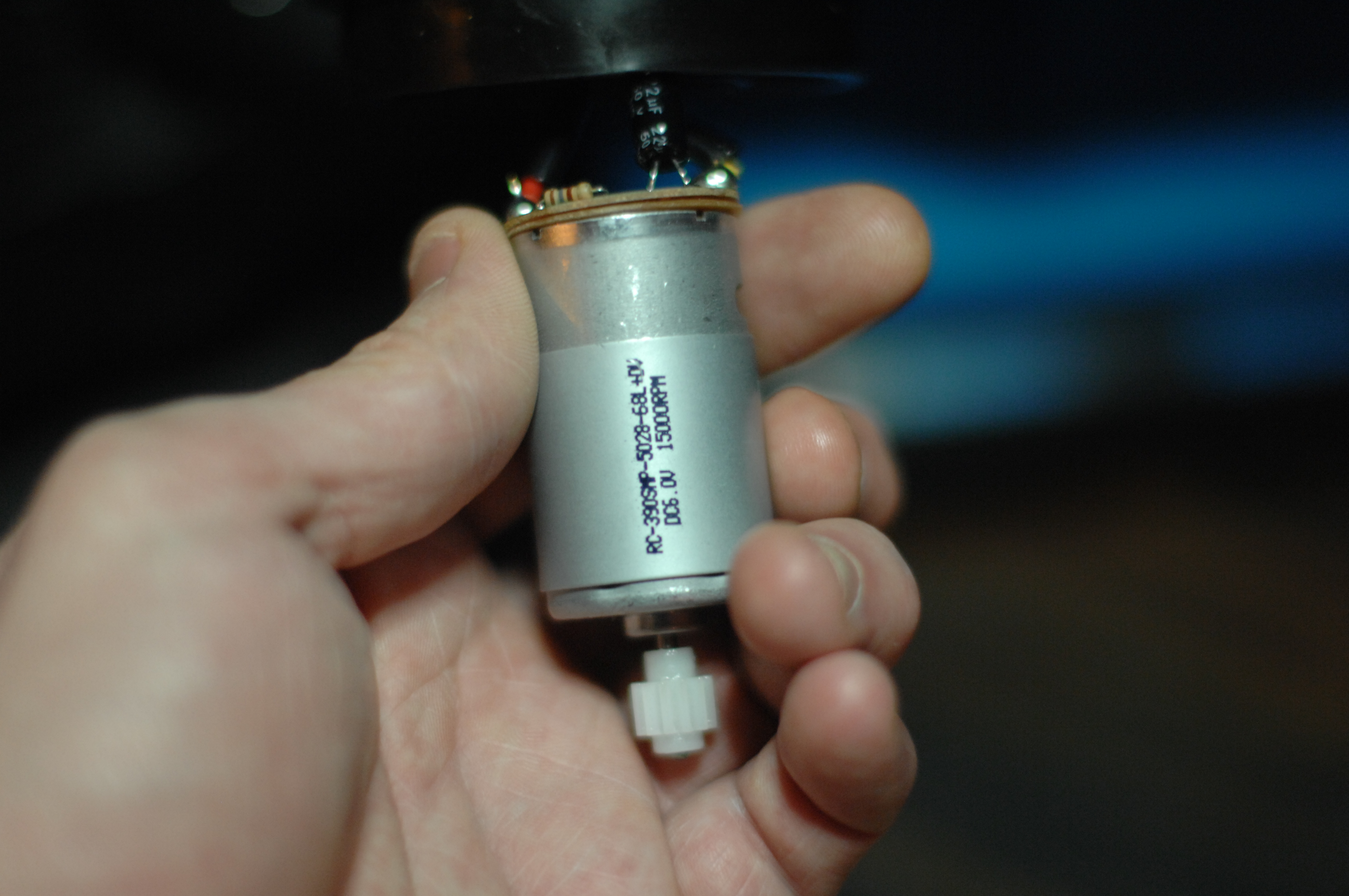
It cost about 250 euros and can be driven from the car or controlled by remote. The car has 3 emulated gears, each allowing the motors to higher rpm's the higher the gear. I say motors, because this model have 2 separate 6 v engines (of type 380/390) which are serial-connected to the 12 volt relay in the receiver. The top speed is 5 km/h. The engines the car came with:
RC-390SMP-5028-68L DC6.V 15000RPM
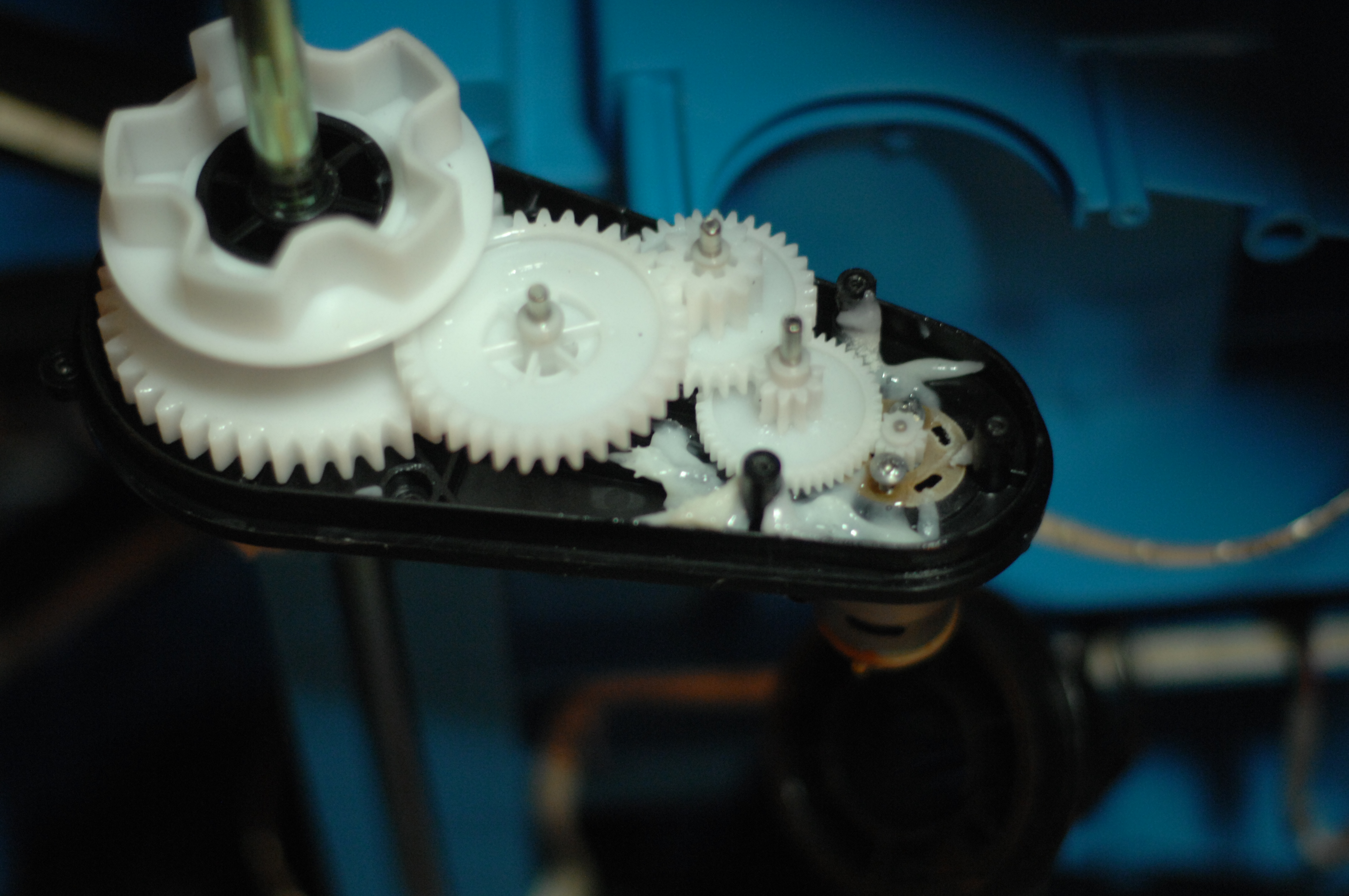
Gearboxes use all-plastic cogs, which is all good in its original state, but this might have to change to support what I want to do:
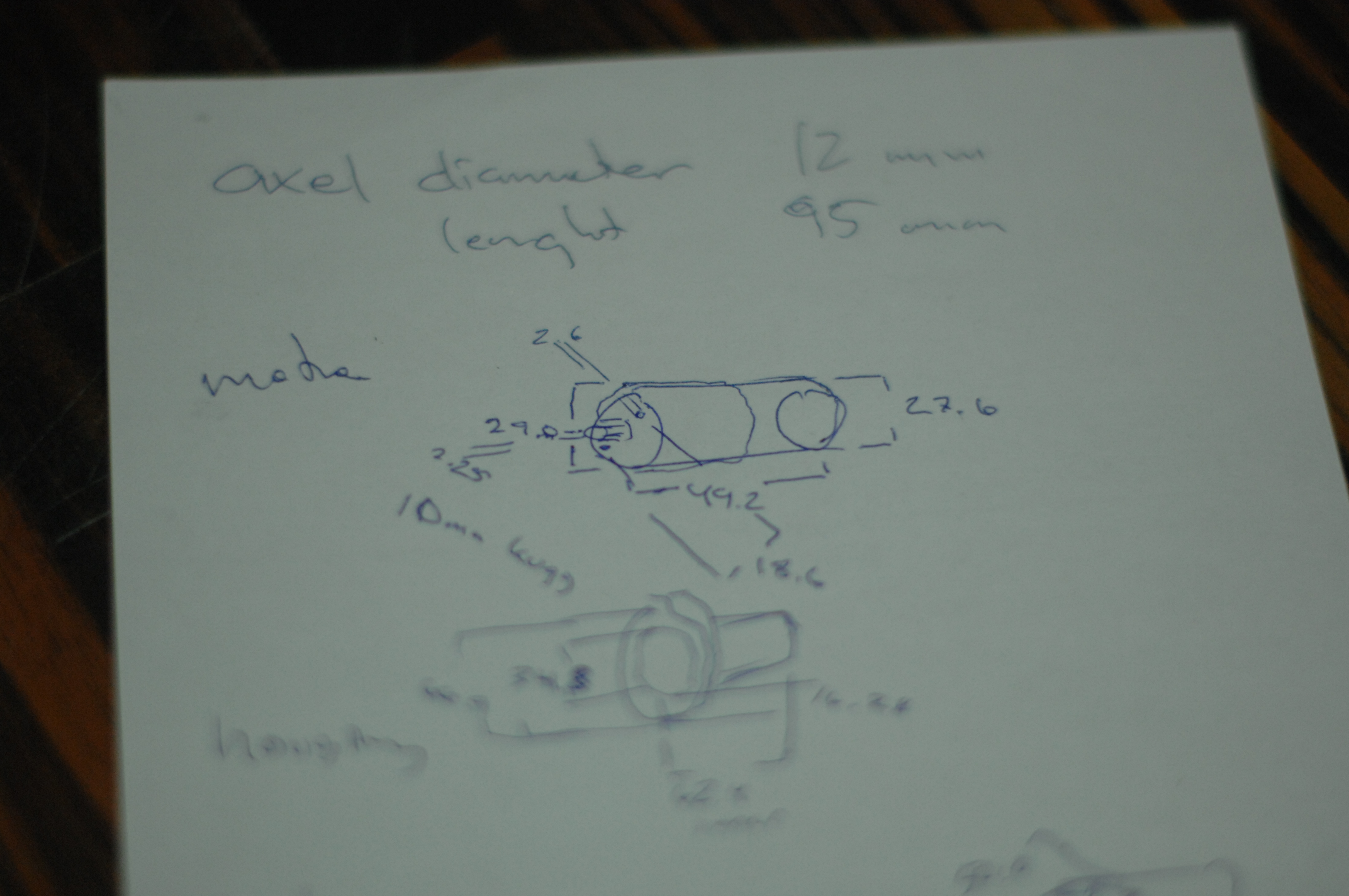
Knowing nothing about the motors (initially that was) I took some measurements and started to google:
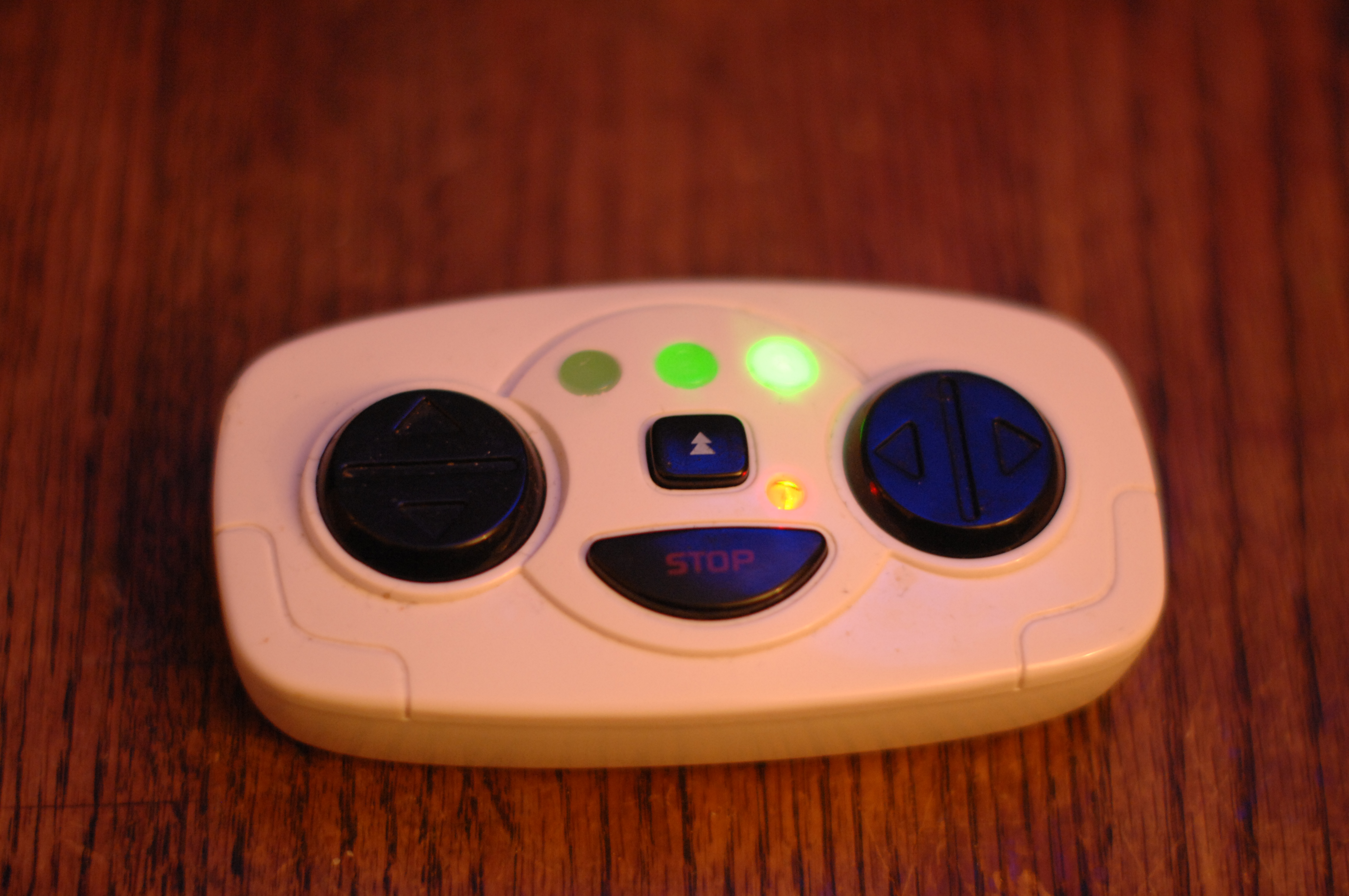
The controller is kind of a all-or-nothing switches, which makes you zig-zag to the left and the right to keep a straight line while driving it using RC along narrow curbs. They added a acceleration lag in the power-on to soften the jerkiness a bit, but unfortunately they didn't manage to do the same when dropping the gas, so stopping is pretty abrupt.
Additionally it has a 6 songs "stereo" , with a 3.5 mm stereo-plug. The songs are well composed mixture between kids music and electronic dance but 6 songs gets boring fast so this is on the change list. When pushing the start-button you hear a roar of the motor, and pushing the horn makes a "mepp-mepp-mep-mep" tone.
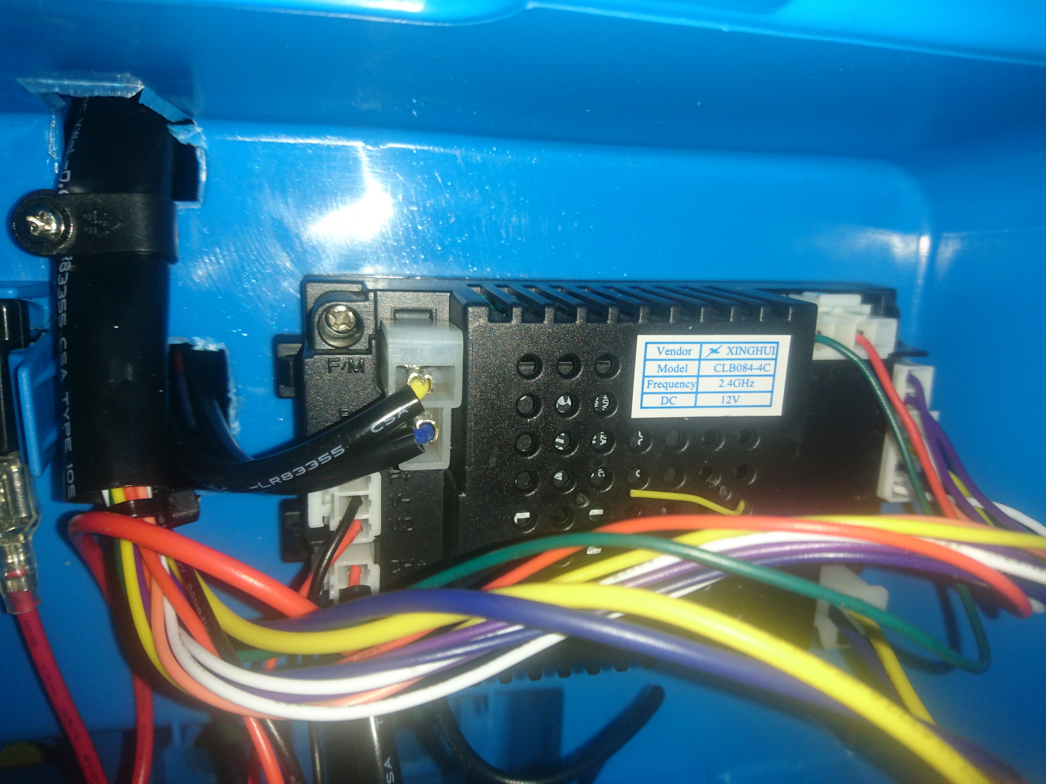
Xinghui CLB084-4c 2.4 ghz receiver, charger, motor controllers and stereo.
The receiver can be found on Aliexpress, but a pdf with all pinouts have turned out to be harder to get my hands on. That sucks, as I see pins that are unused meaning it might have more features I don't know yet.
Will reverse engineer it later. All in all it's a funny toy for its price but a lot of improvements can be done.
So what am I planning to do with it?
Well, I have a lot ideas but some cost a bit of money and some are hard to source parts for and some will simply be unsafe.
It should be a little faster, with softer acceleration and braking.
Replace the radio-controller/receiver, with something a bit more professional, less jerky and with lots of spare channels to control all the electronics.
Proper rubber tires giving traction and look better. A few options out there, but I haven't found exactly what I want. A proper stereo with some umpff!
Individual brake disks on the front wheels to be able to do burnouts.
Melody horn.
Proper seat-belt 3 or 4 point, new seat even?
Let's get started.
The first thing that struck me when I started screwing it apart was how much space there is left in it.
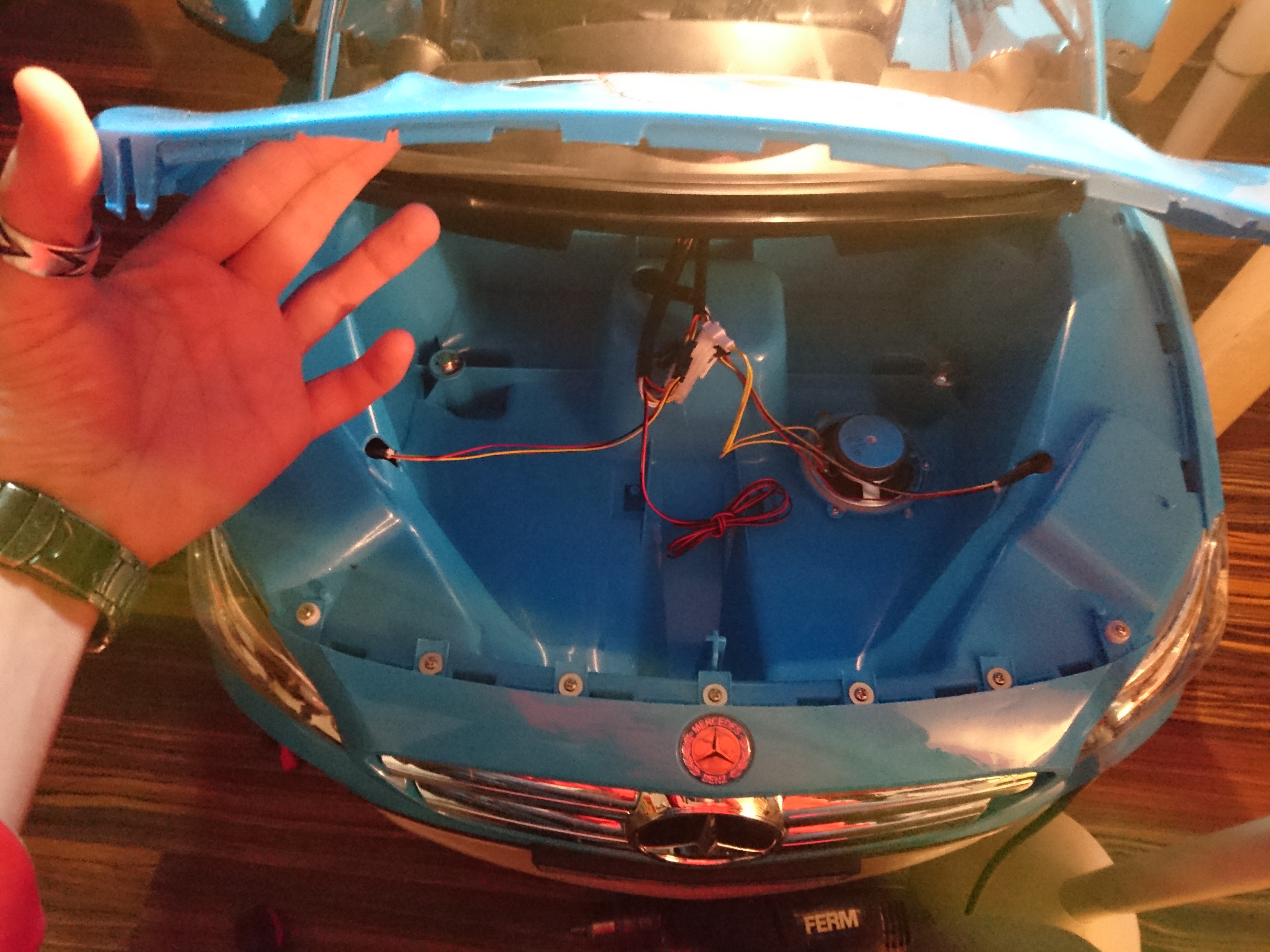
The hood is screwed down, but once unscrewed yet another gigantic rather empty space is revealed. Same goes for the trunk. Ohhh the potential :)
So where does one start?
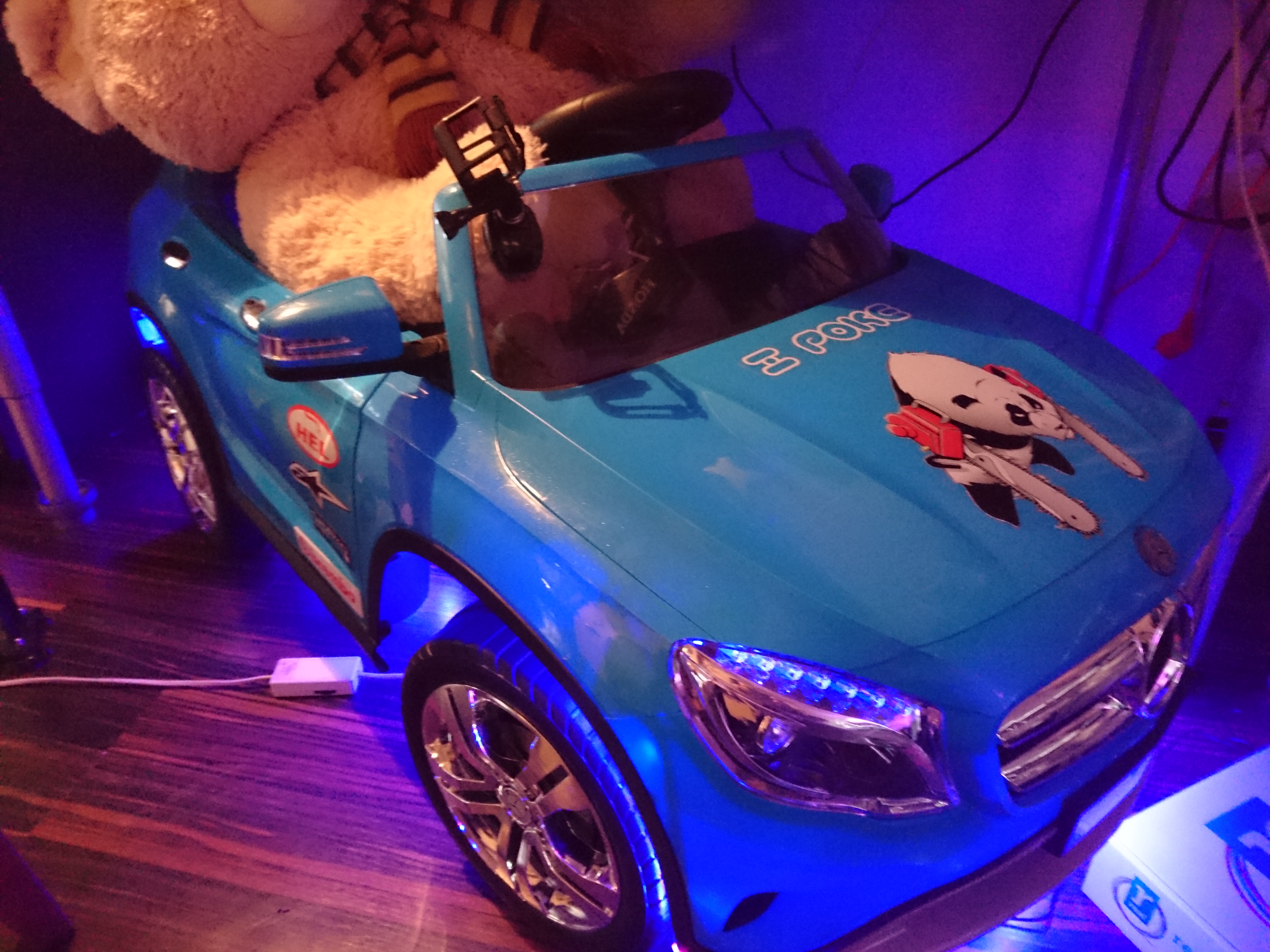
Let's go with the low-hanging fruit. Nothing says car-tuning like RGB LED-stips, and it's something my son would notice directly so that's what I went for. End result looks (and sounds) something like this (hosted video on youtube, as I slashdotted my hosting company yesterday thanks to HackerNews):
A second fast win would be stickering it with some AlpineStars, Brembo, Hel performance and GoPro stickers.
I had a left-over "I poke bear"-sticker from the pimping of my zx636 ninja, so that went on the hood too.
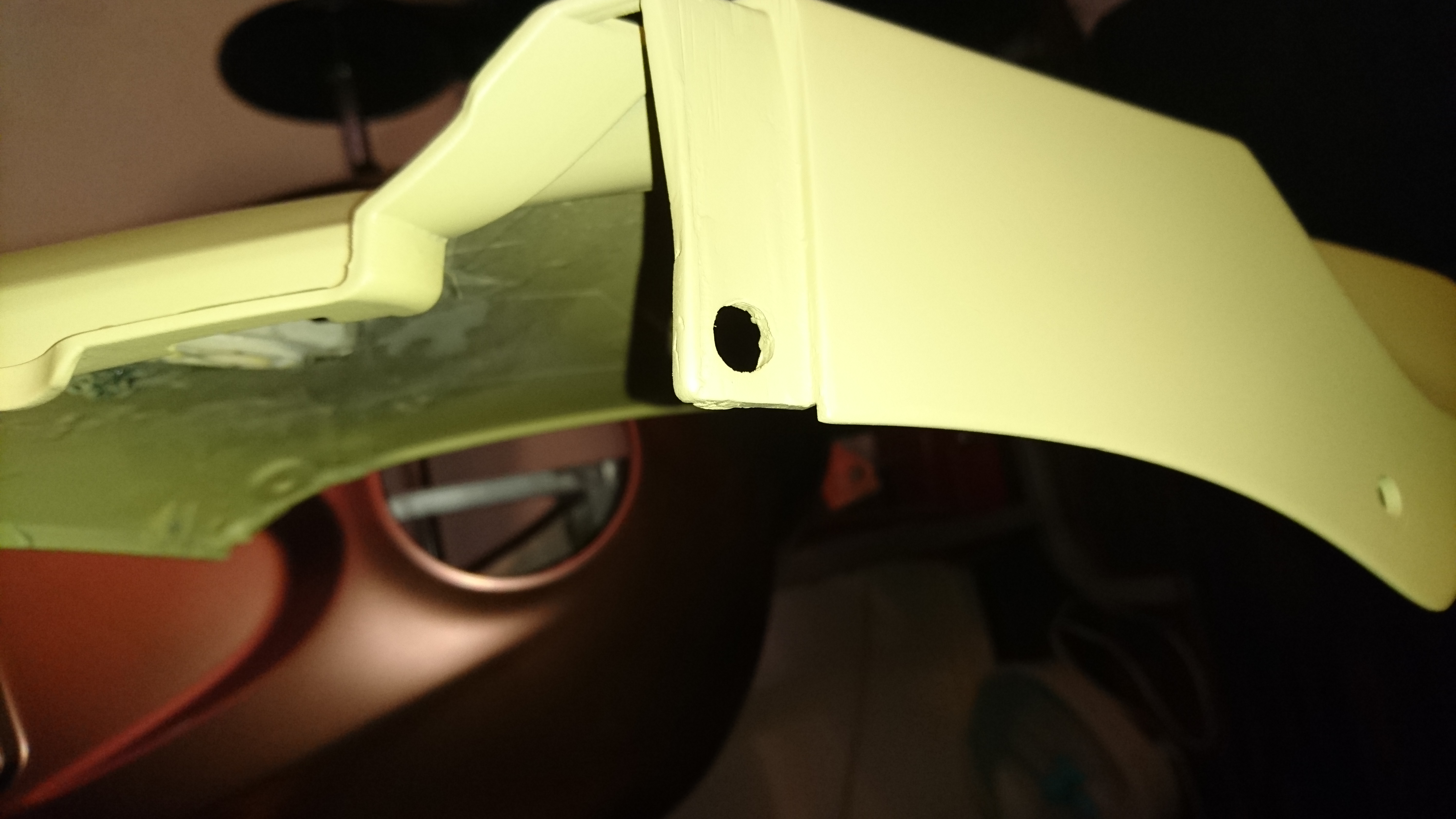
Speaking of the hood, I mentioned I opened it up however seeing the hood open made me think it should not be screwed down ever again. I made 2 temporary hinges with a glue-gun and two screws, and cut off the majority of all the flanks that held the hood into place making the area easily accessible for future upgrades.
The open hood reveals a lot of free space and a mono speaker.
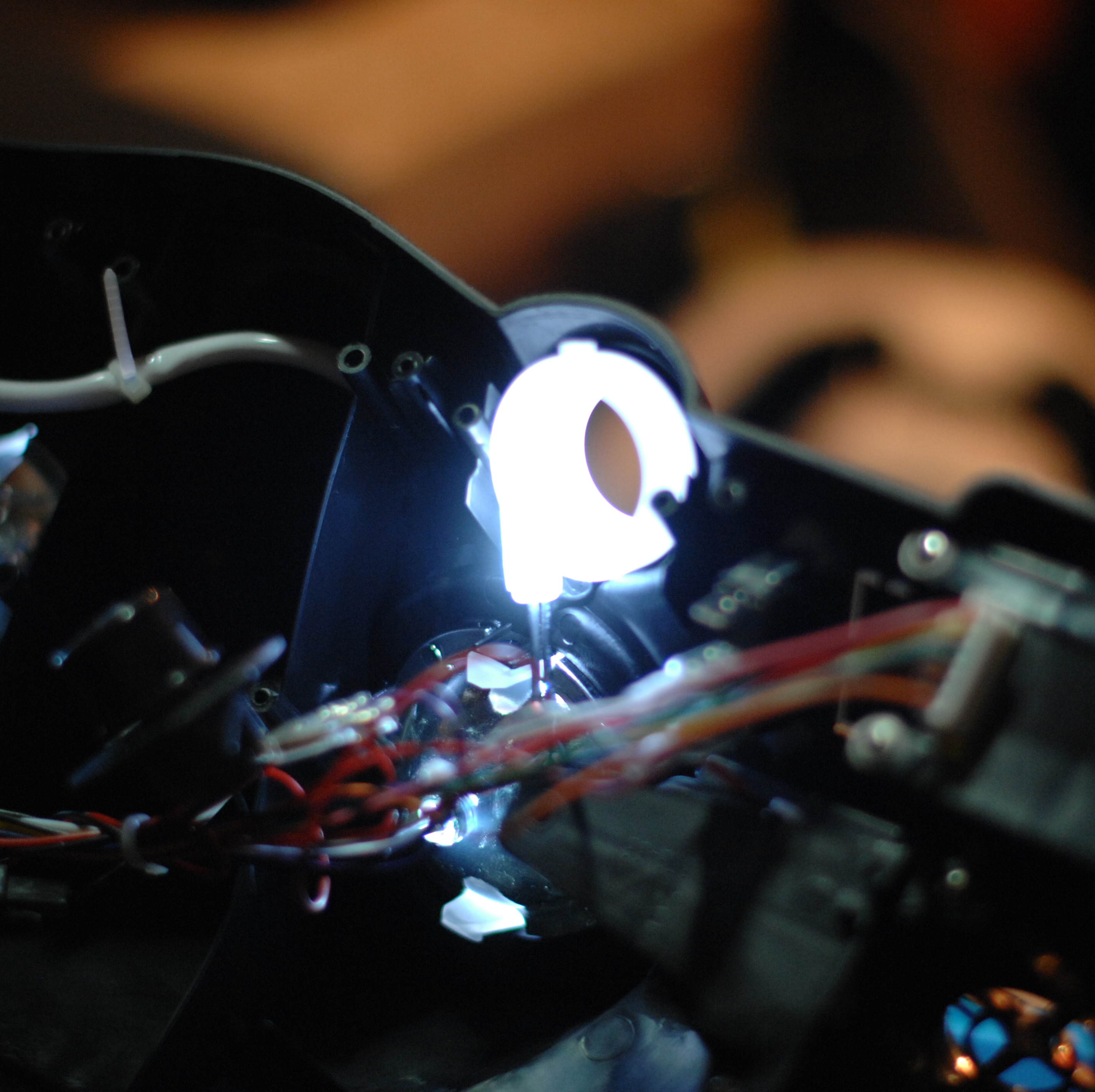
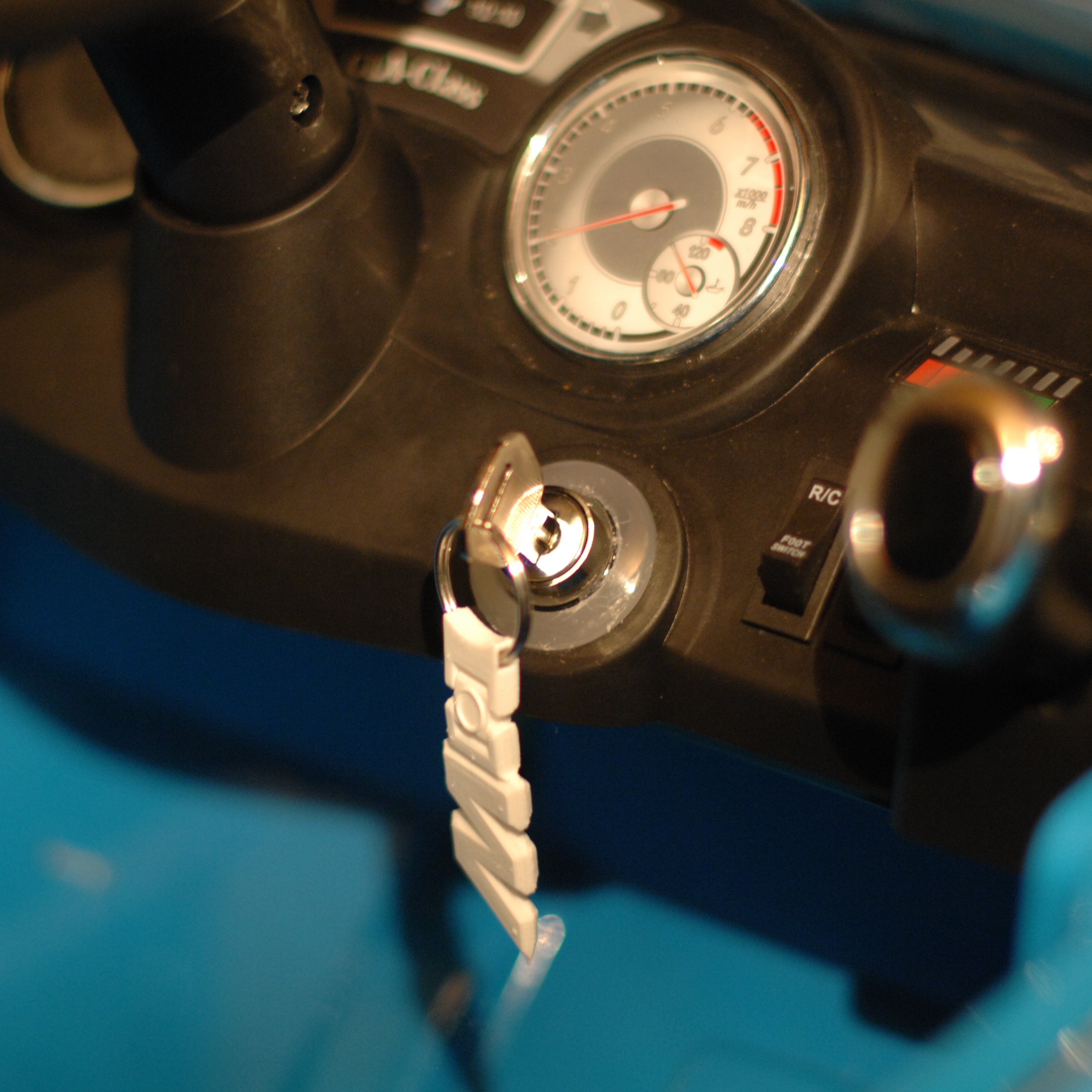
Ignition-switch:
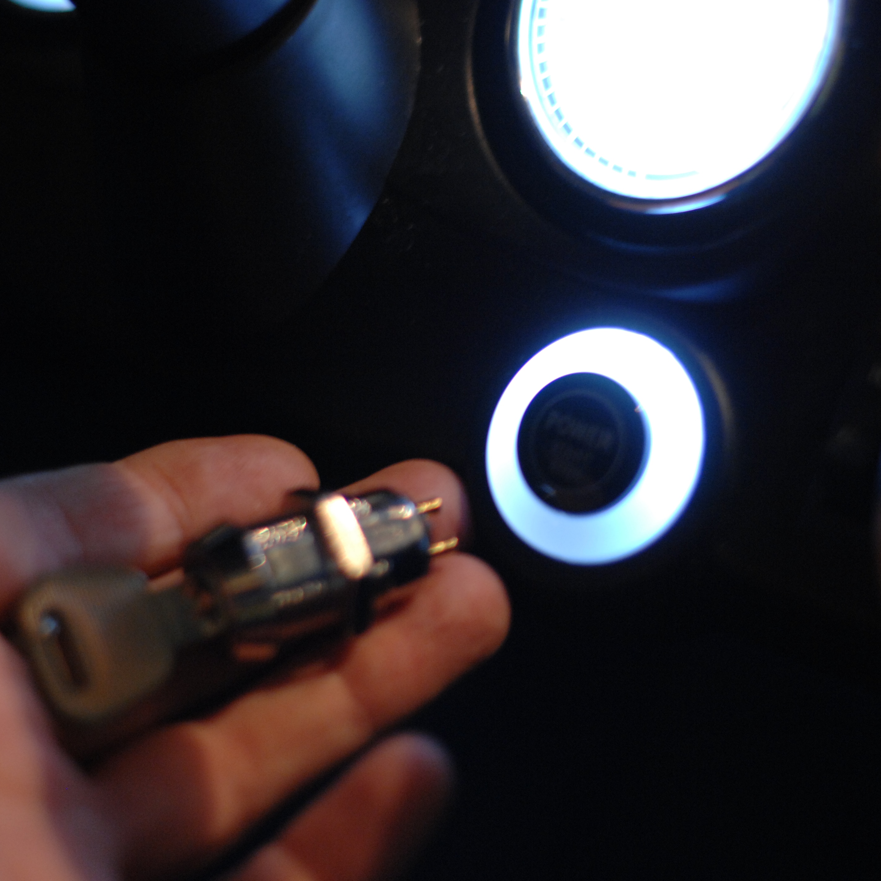
My little guy is totally fascinated by keys, so needless to say he needs an ignition-key. I found this little switch in one of my favorite stores around the corner, Rotor-radio Amsterdam.
To get it into the car, I had to unscrew large parts of the car.
Then solder it into the harness where the old switch was connected.
Tada!
Reversing camera.
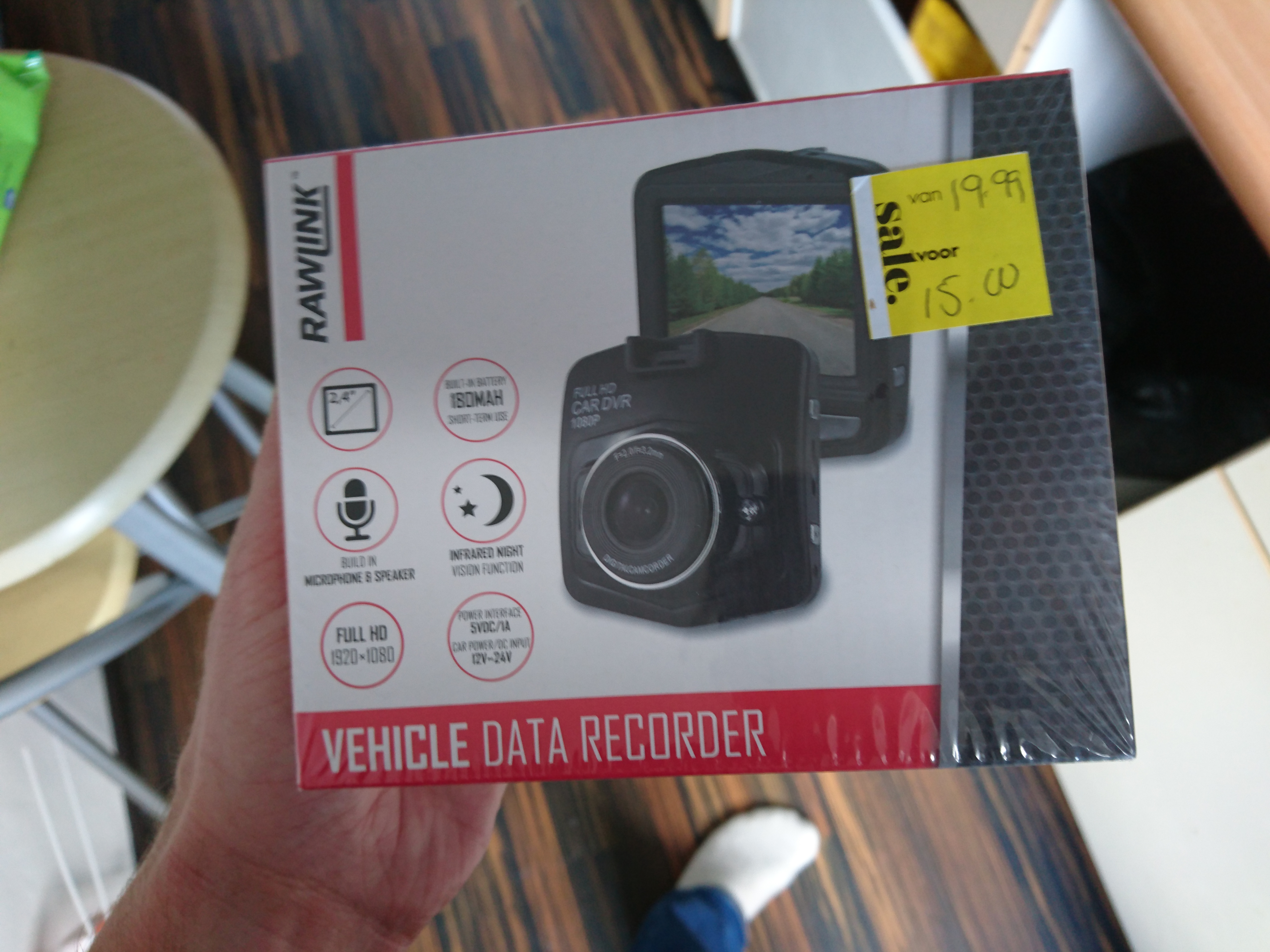
I found this super-cheap dashcam, and decided it would make a great rear reverse camera:
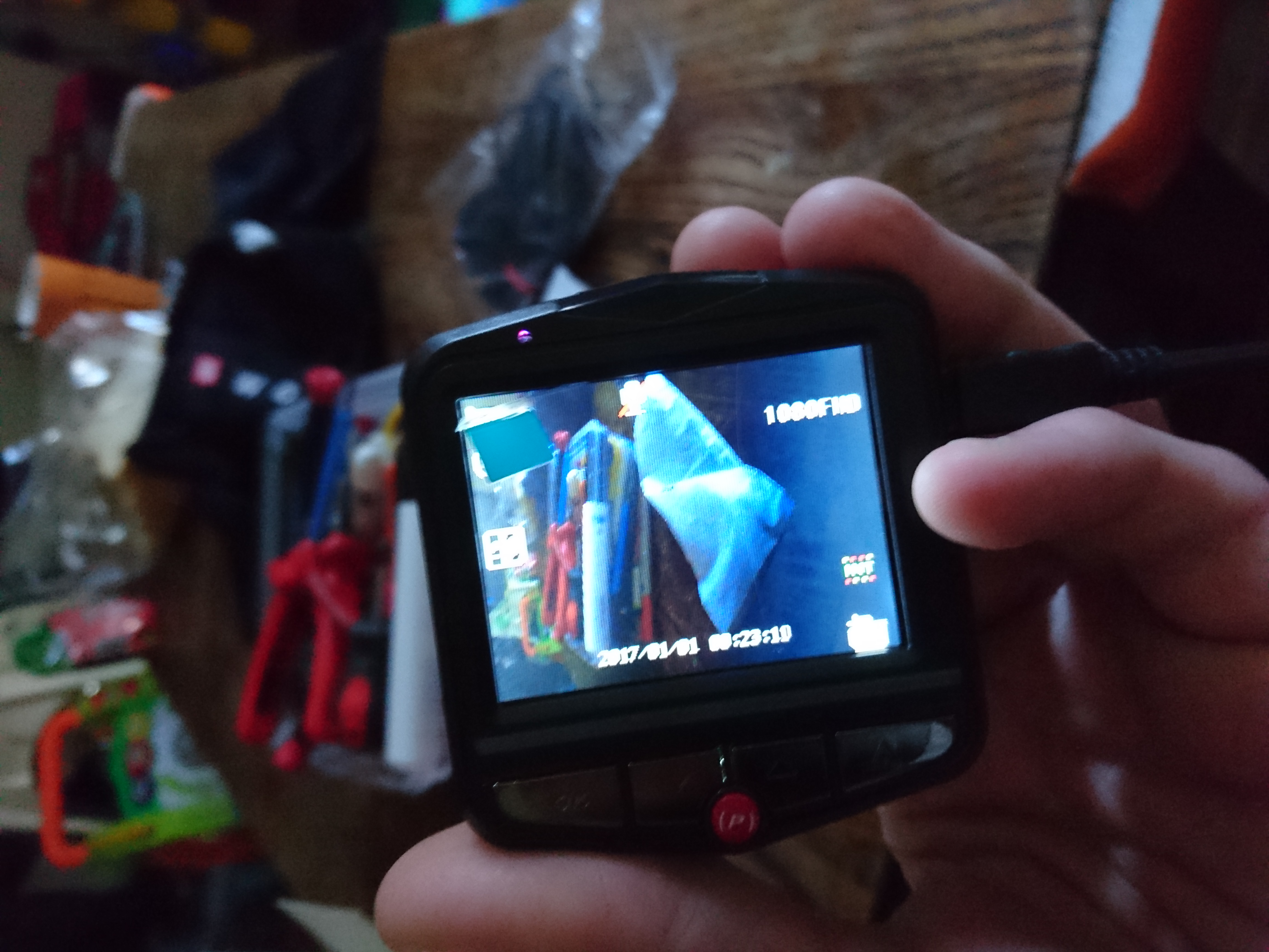
Quality of the picture is great and it also has night-vision :)
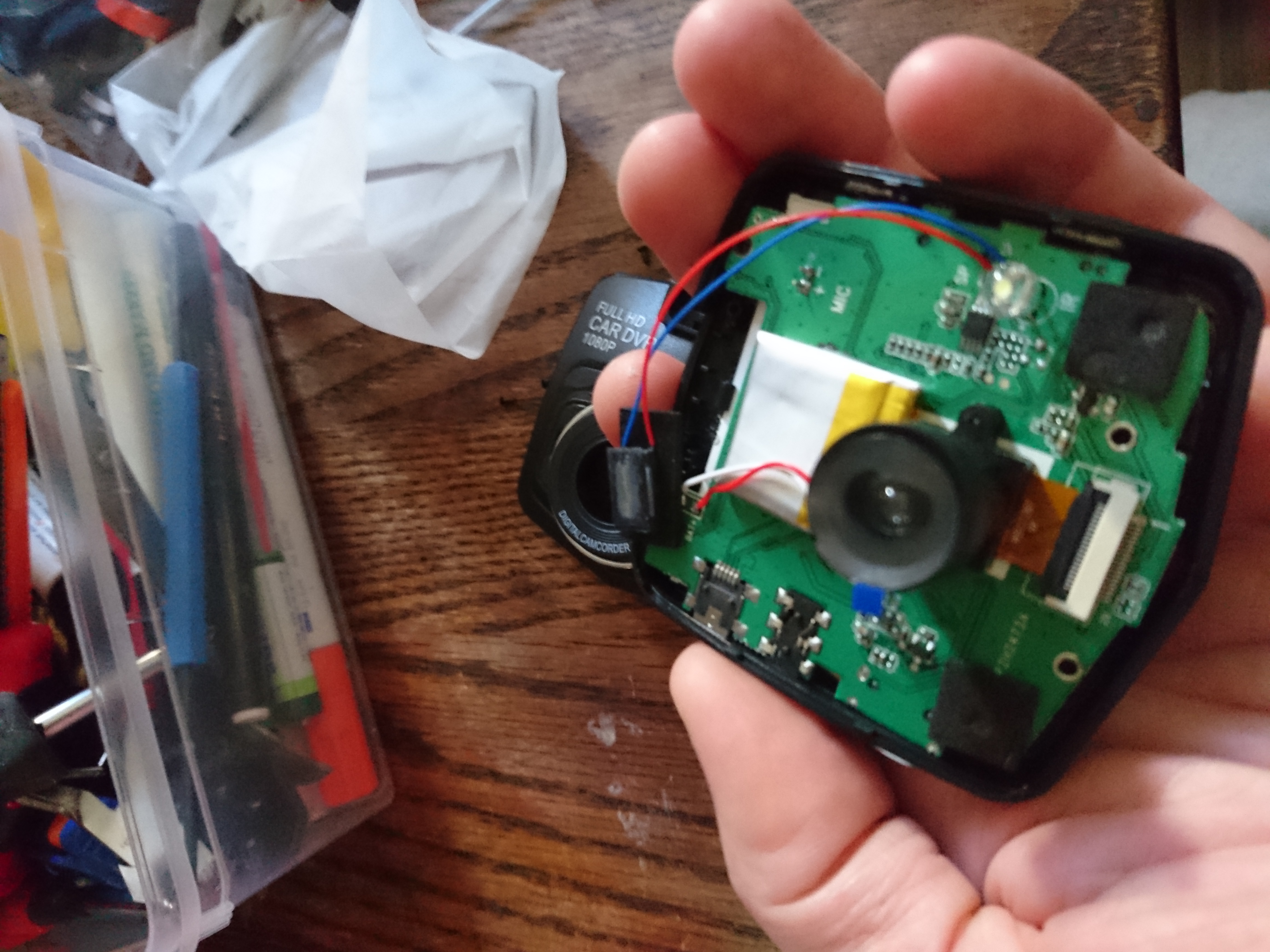
Opening it up, shows I will have to solder 17 wires to separate the camera from the circuit-board:
Not impossible but since I intend to install a proper stereo in the dash too, it makes sense putting this on ice until that is done and I know how much space is left.
I got the power!
So far I have not run into the limitations of the battery, but my son is quite young and we only do small rounds with it. However I plan to stick a lot of electronics in this beast so a larger battery makes sense.
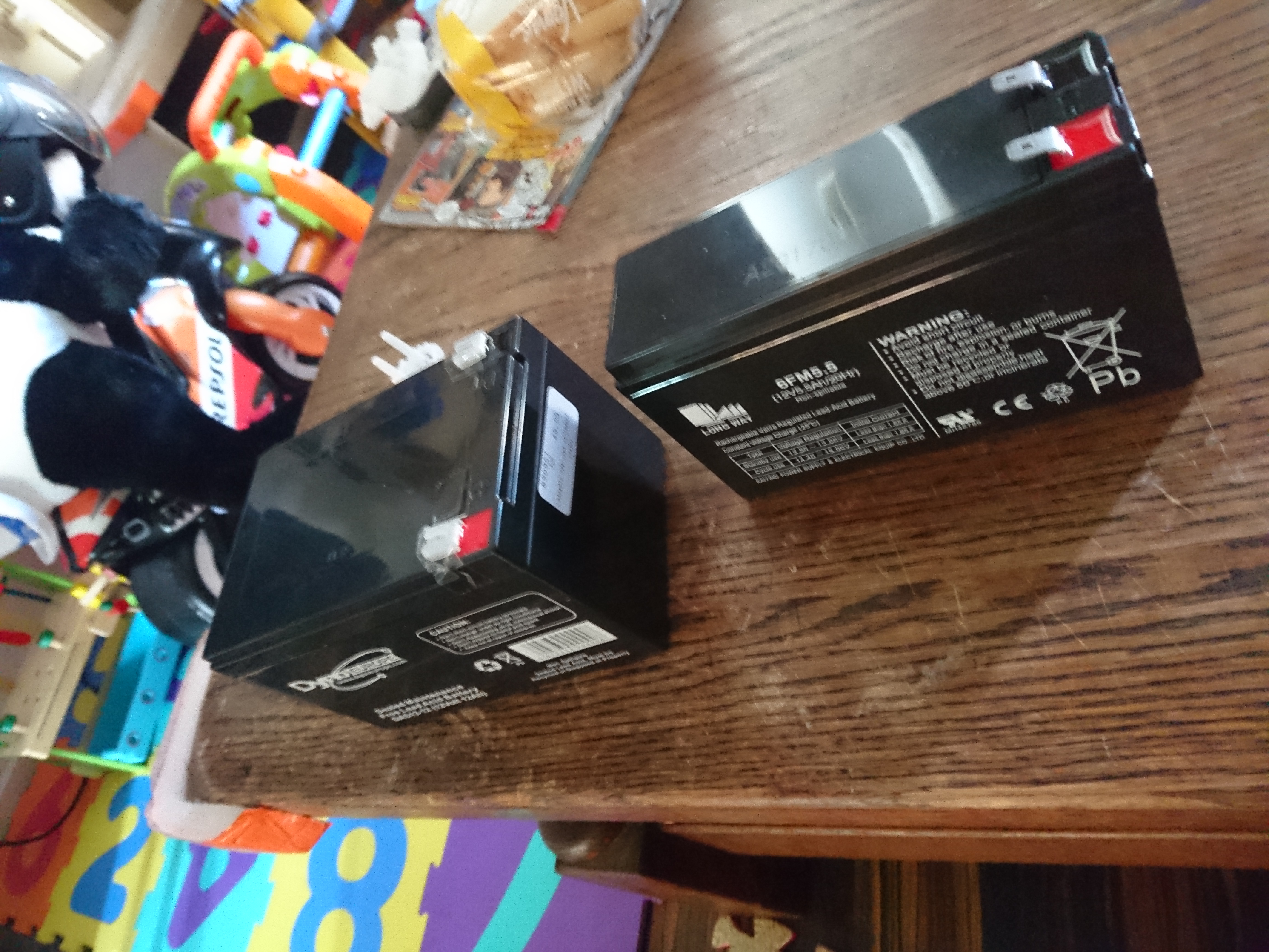
The car actually had room for the larger battery where the old one was mounted
I replaced the 5.5Ah 12 volt lead-acid with it's 12 Ah big brother.
Battery upgrade
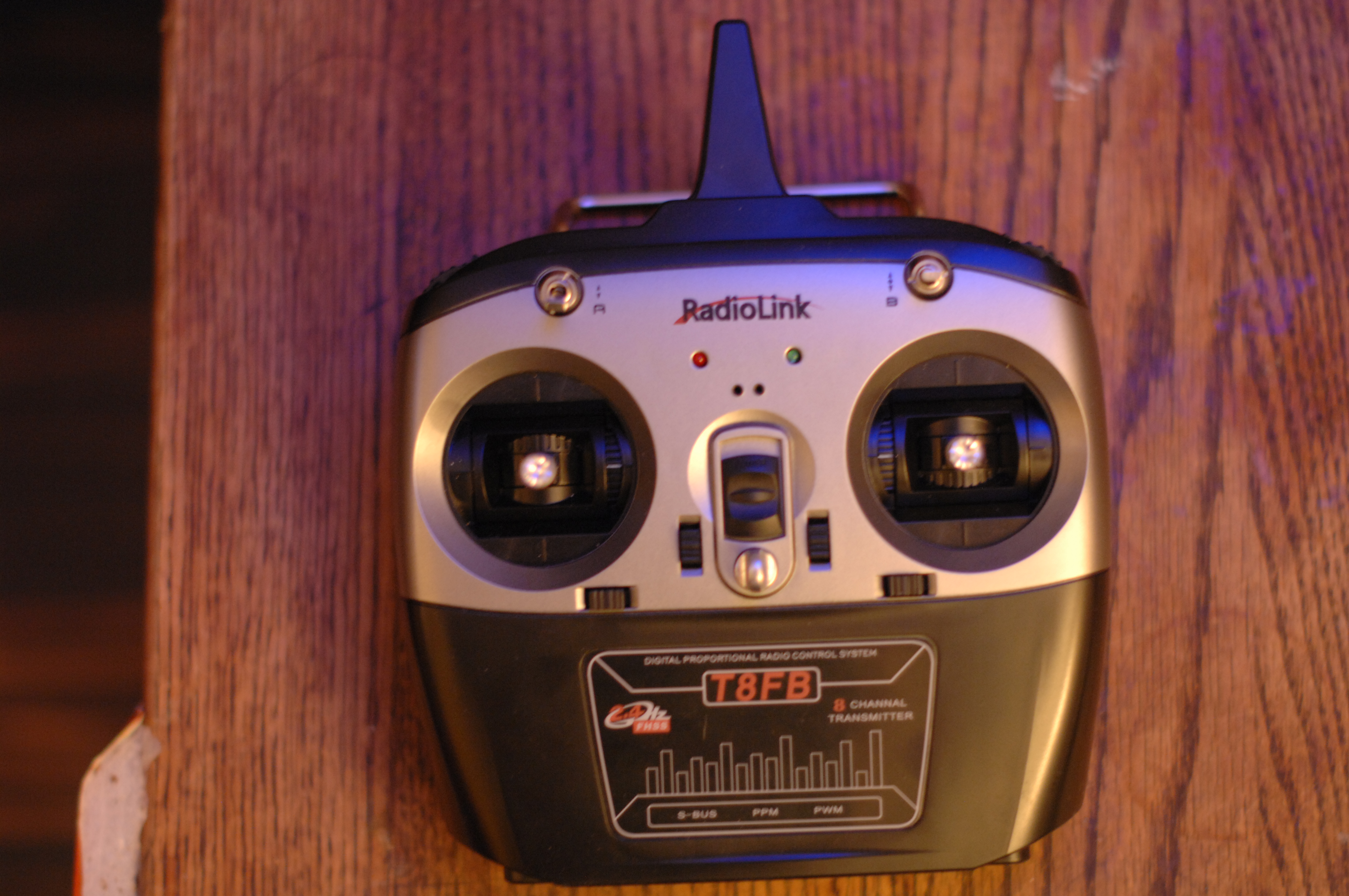
With brakes, LEDS and what-not, I decided to buy a 8-channel radio. I can only hope this scales to the ideas I have but we will see:
RadioLink T8FB
Getting the radio ready!
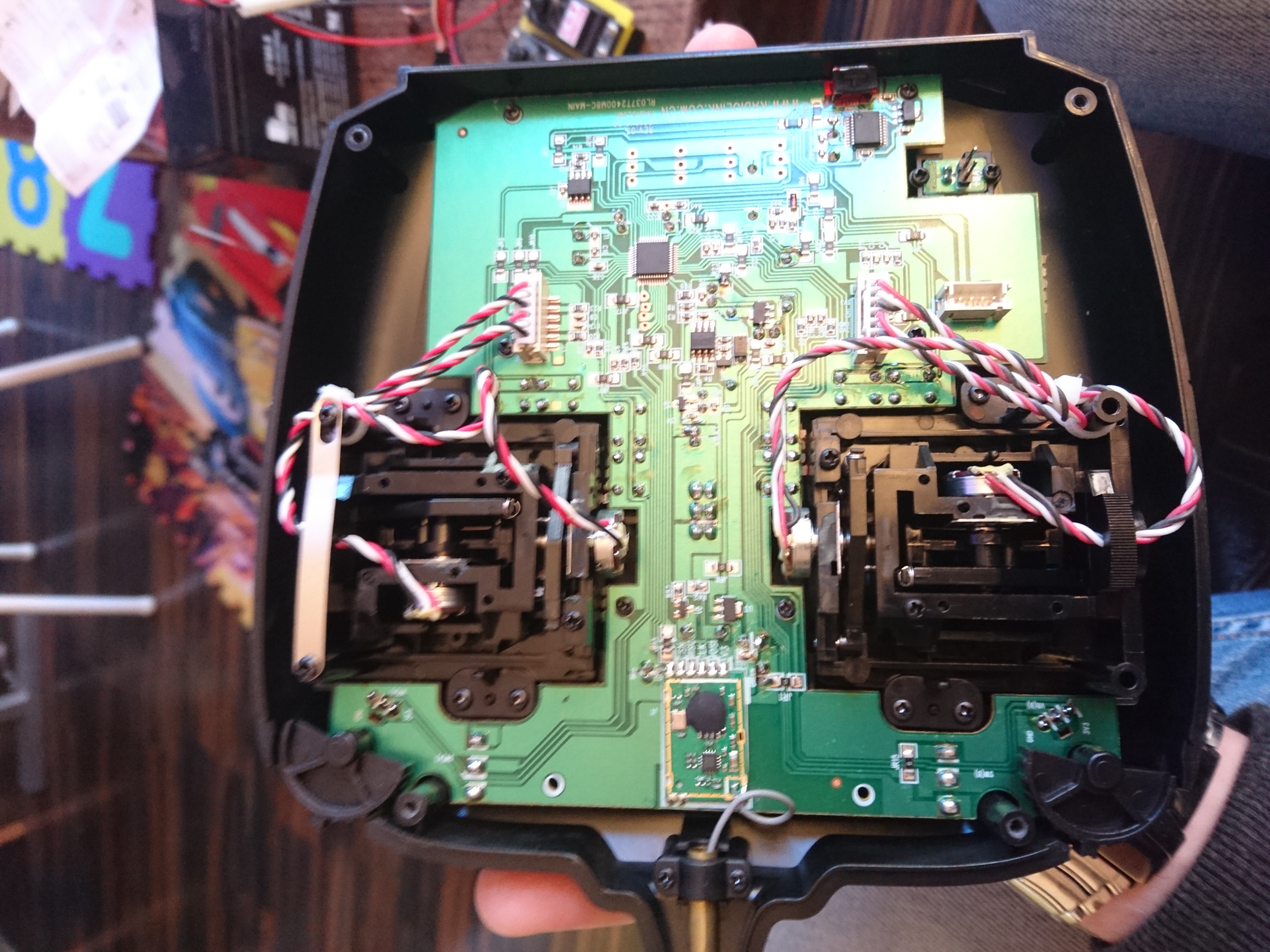
I have never built a radio-controlled car from scratch so selecting ESC, servos, motors, batteries was all done ad-hoc, while googling around. This radio is intended for plane/helicopters, so I started by reconfigured the control to spring back the left hand stick when released:
RadioLink T8FB opened up.
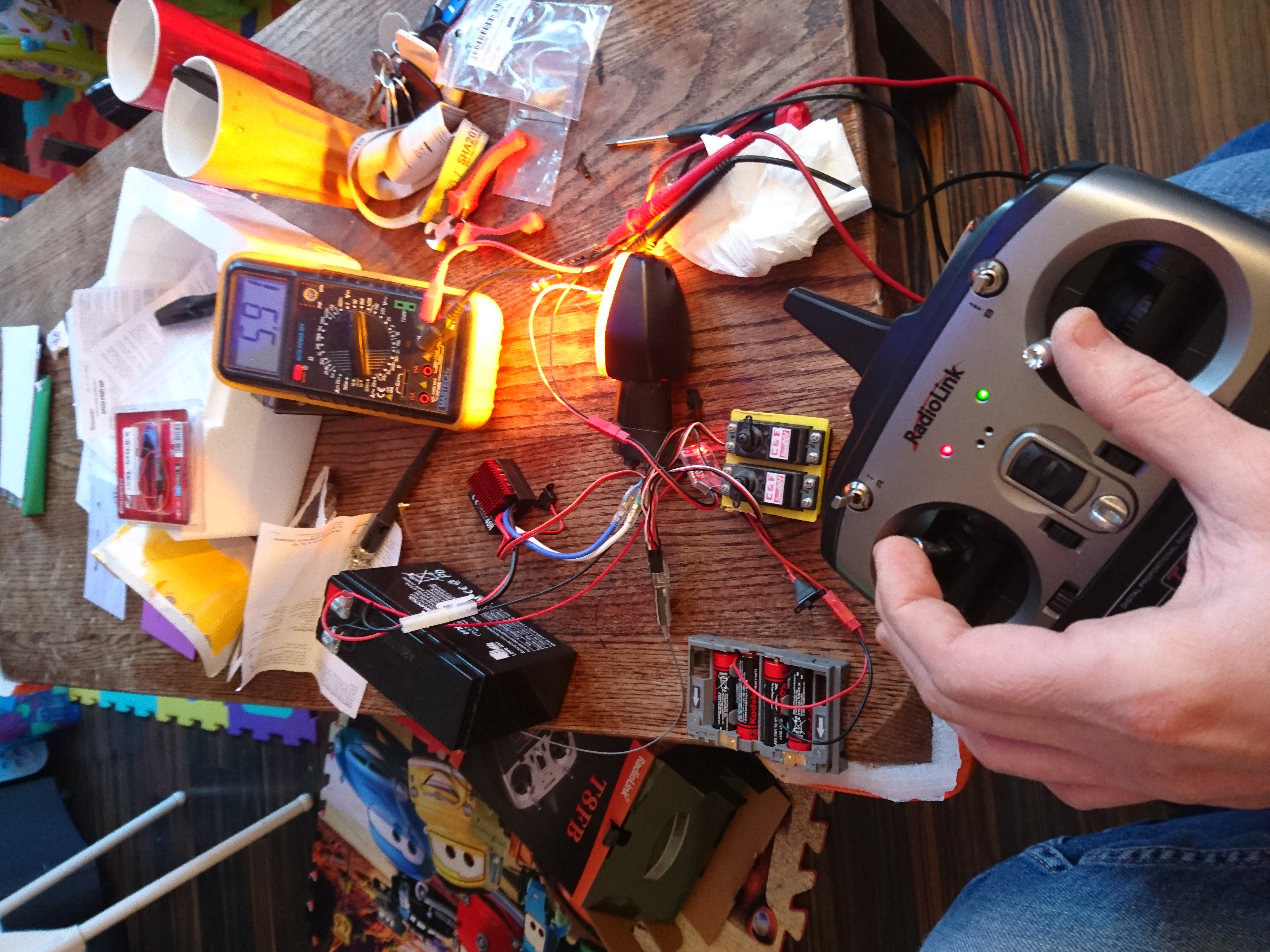
For the drive-line I choose a 40Amp 12 volt ESC from Graphner. Two old servos from a small electric plane simulated the servos for the brake-disks and a smaller ESC to control steering.
The old fireblade blinker is connected to the 40Amp ESC to verify that all works. Having it all on the table like this allowed me to calibrate servo's and ESC's in a simple way.
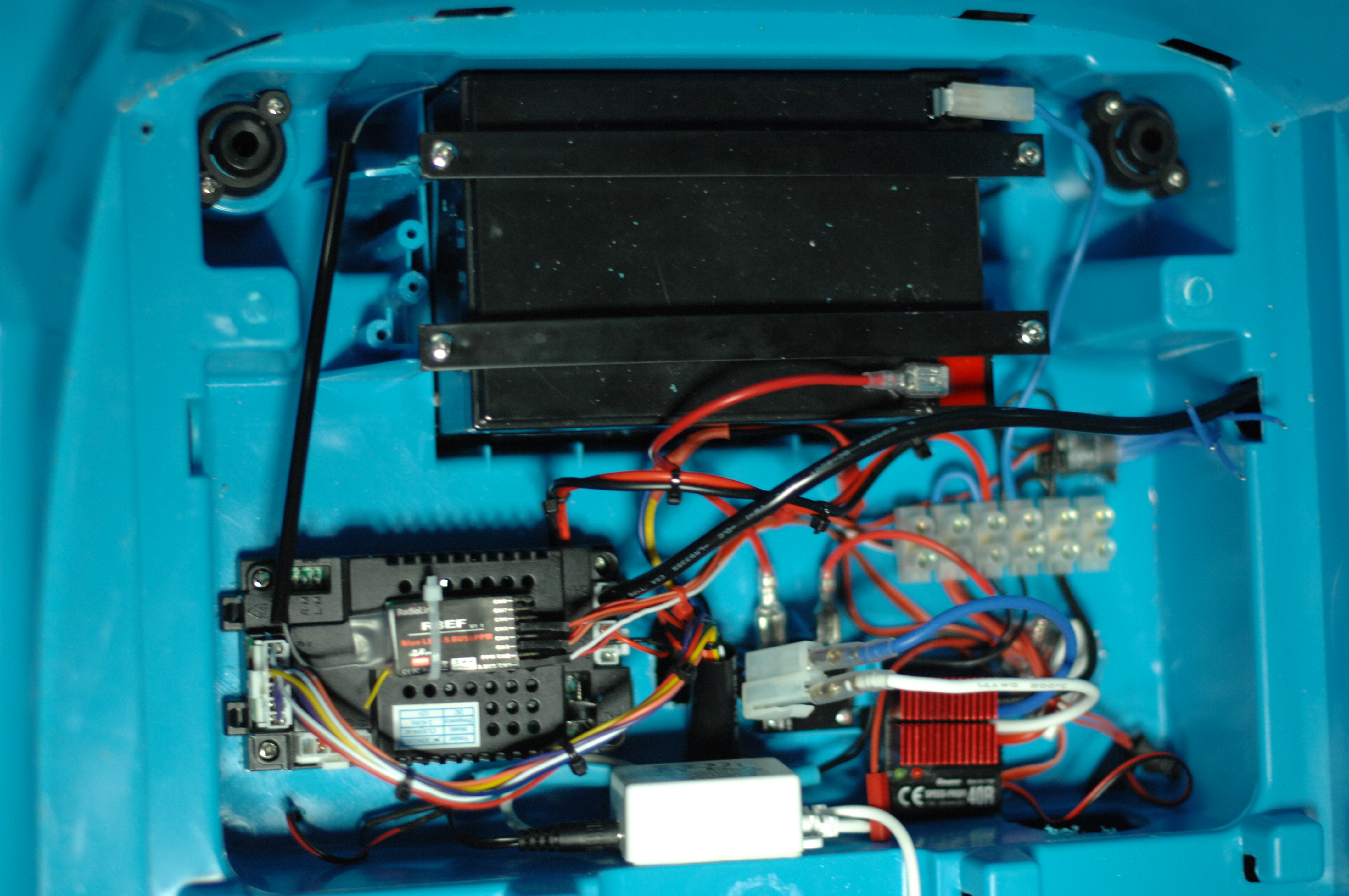
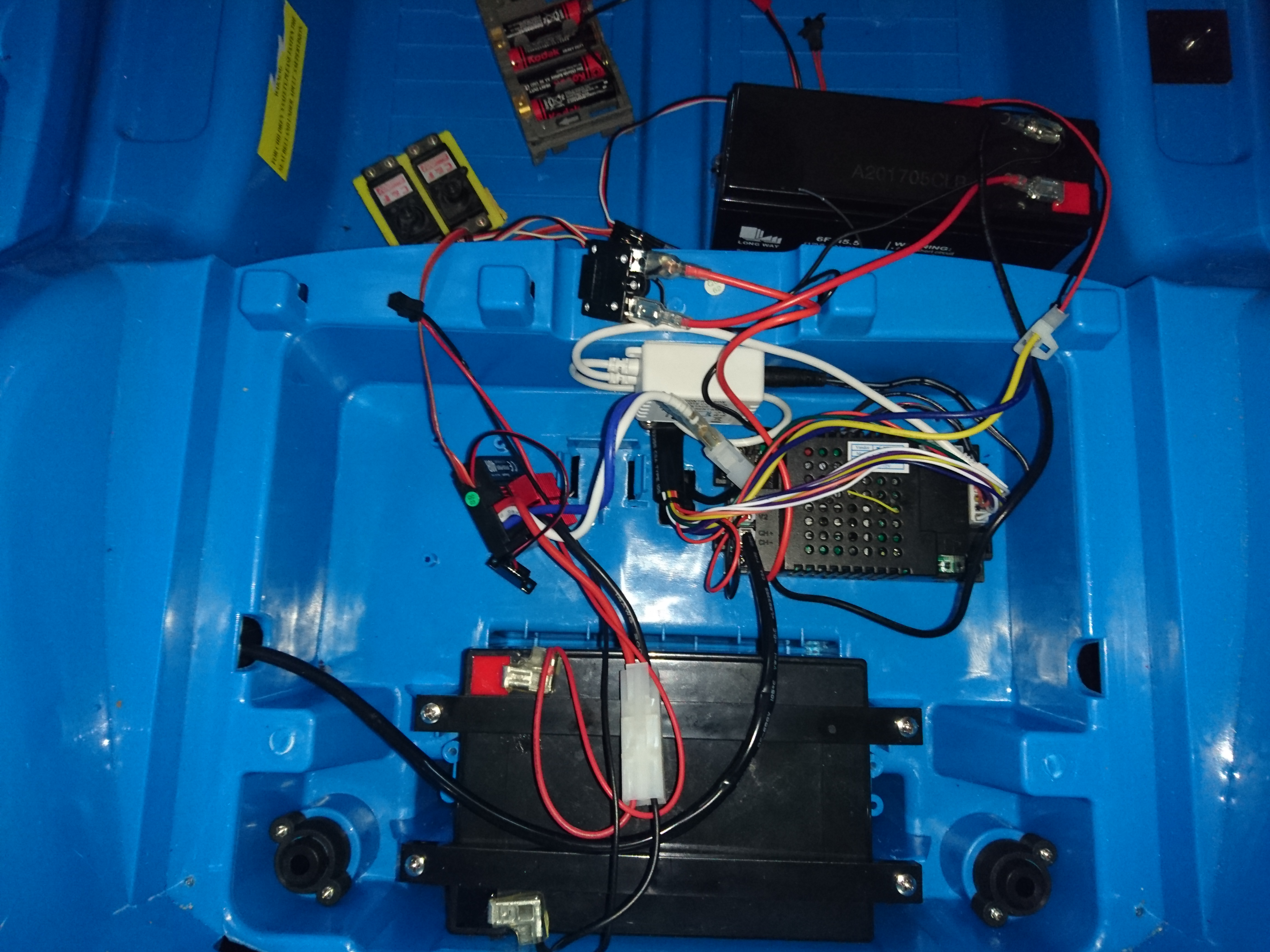
Once that seemed to be working I hooked it up to the car. As my son would be very sad if his stereo did not work, I left as much of the old electronics hooked up in the birdsnest you can see below:
Nested the new rc-parts into the original wiring, and it works.
This means that I now can control the car over the 8 channel radio, while still providing power to the old electronics that allow the fake engine sounds and "stereo" to work.
After a bit of tidying up, it is starting to take shape. Doubt it will look like this when I am done, but lets see.
Can you hear me?
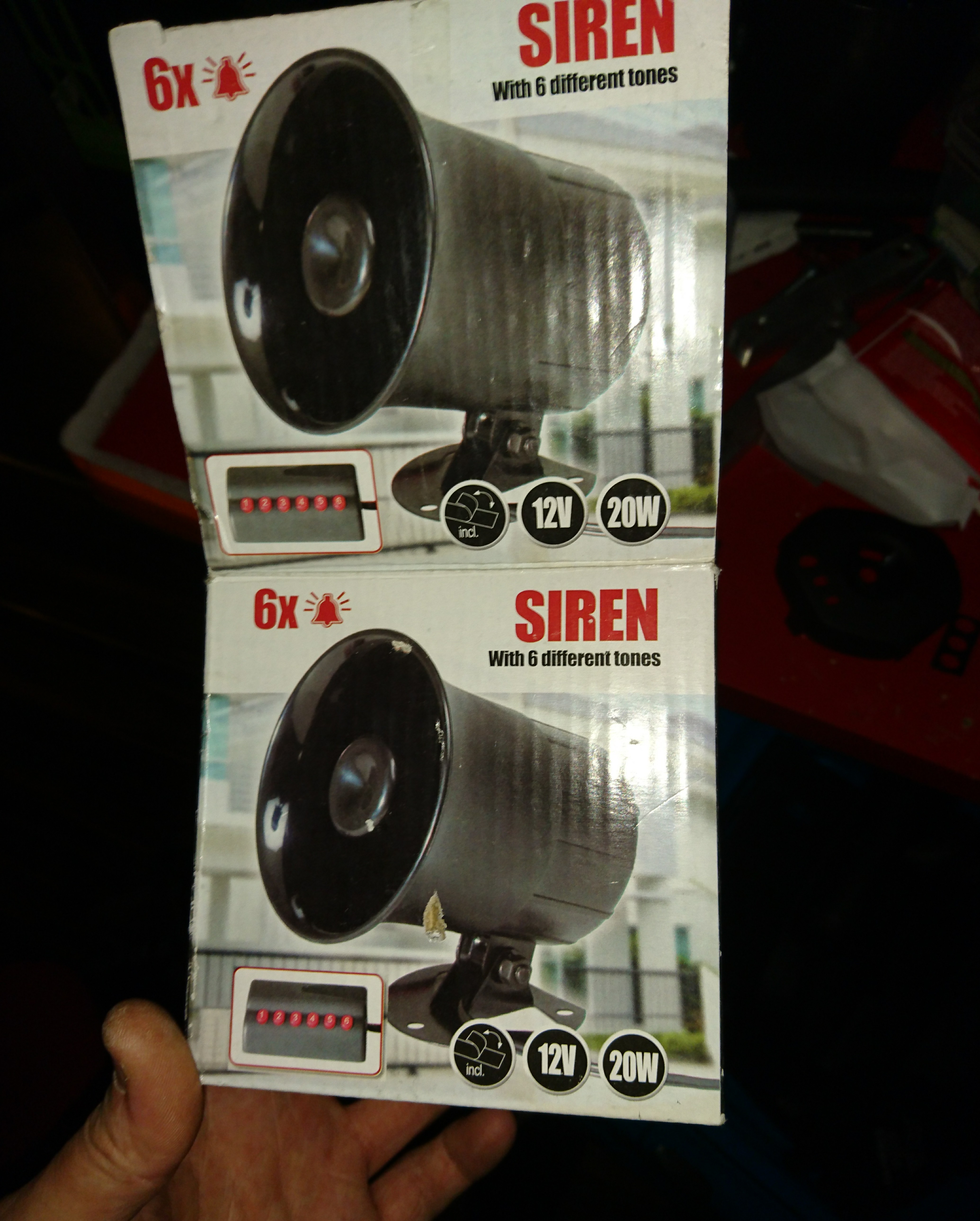
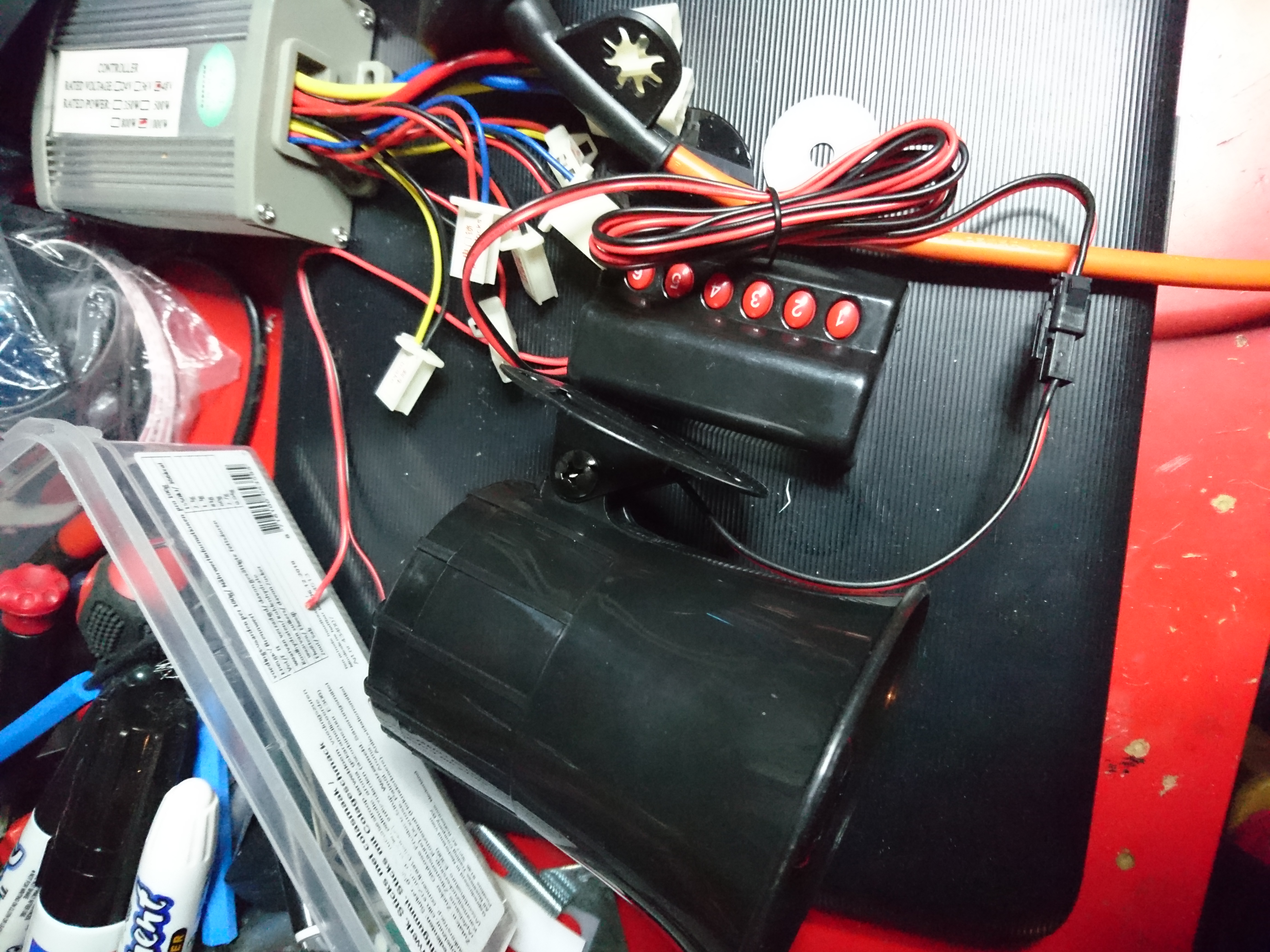
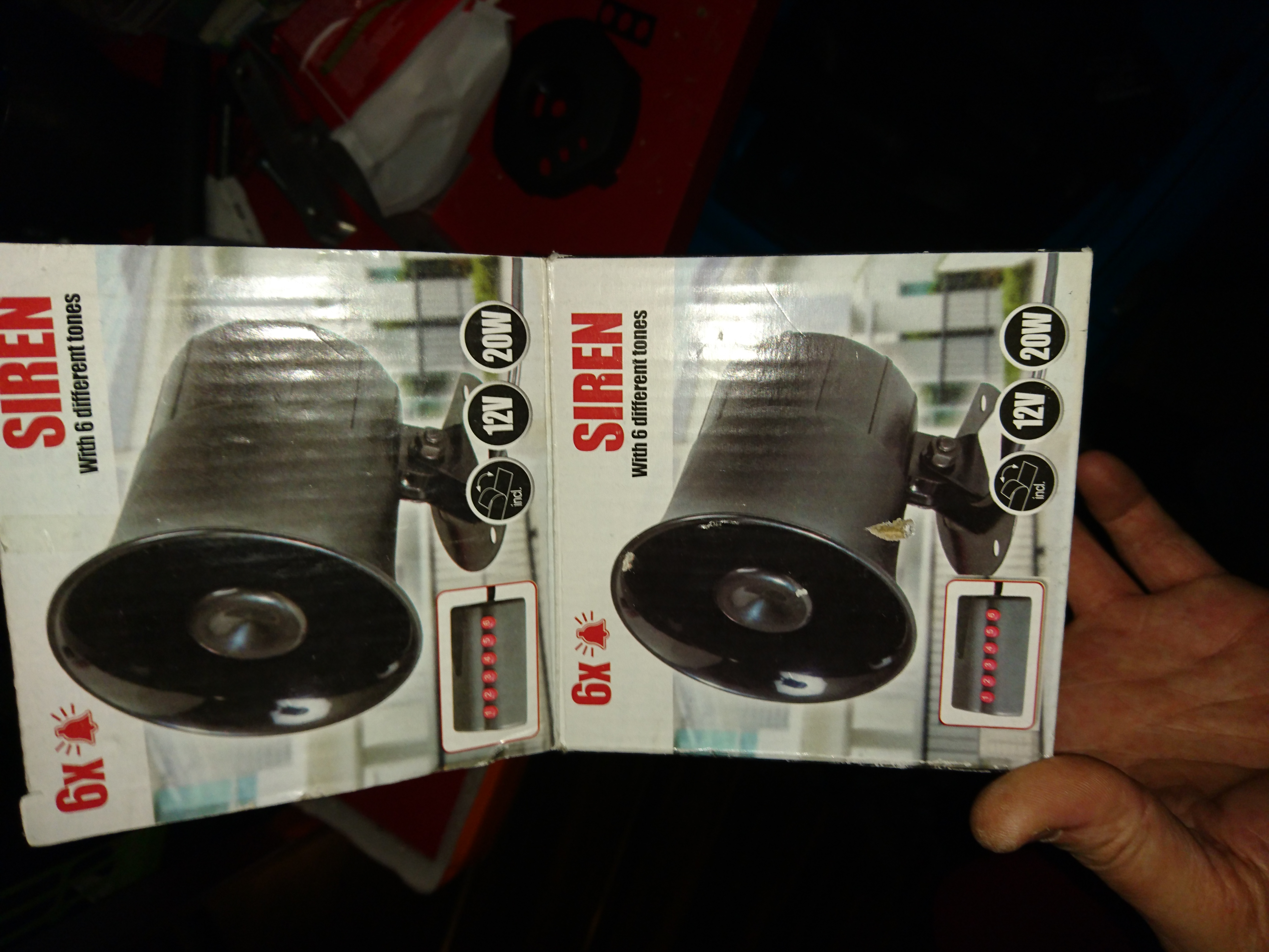
Speaking of sounds needless to say he needs a proper horn. I found this 20 watt siren with 6 tones for less than 10 euros, so that's going in.
I don't know how loud it is, but it's f***ing loud.
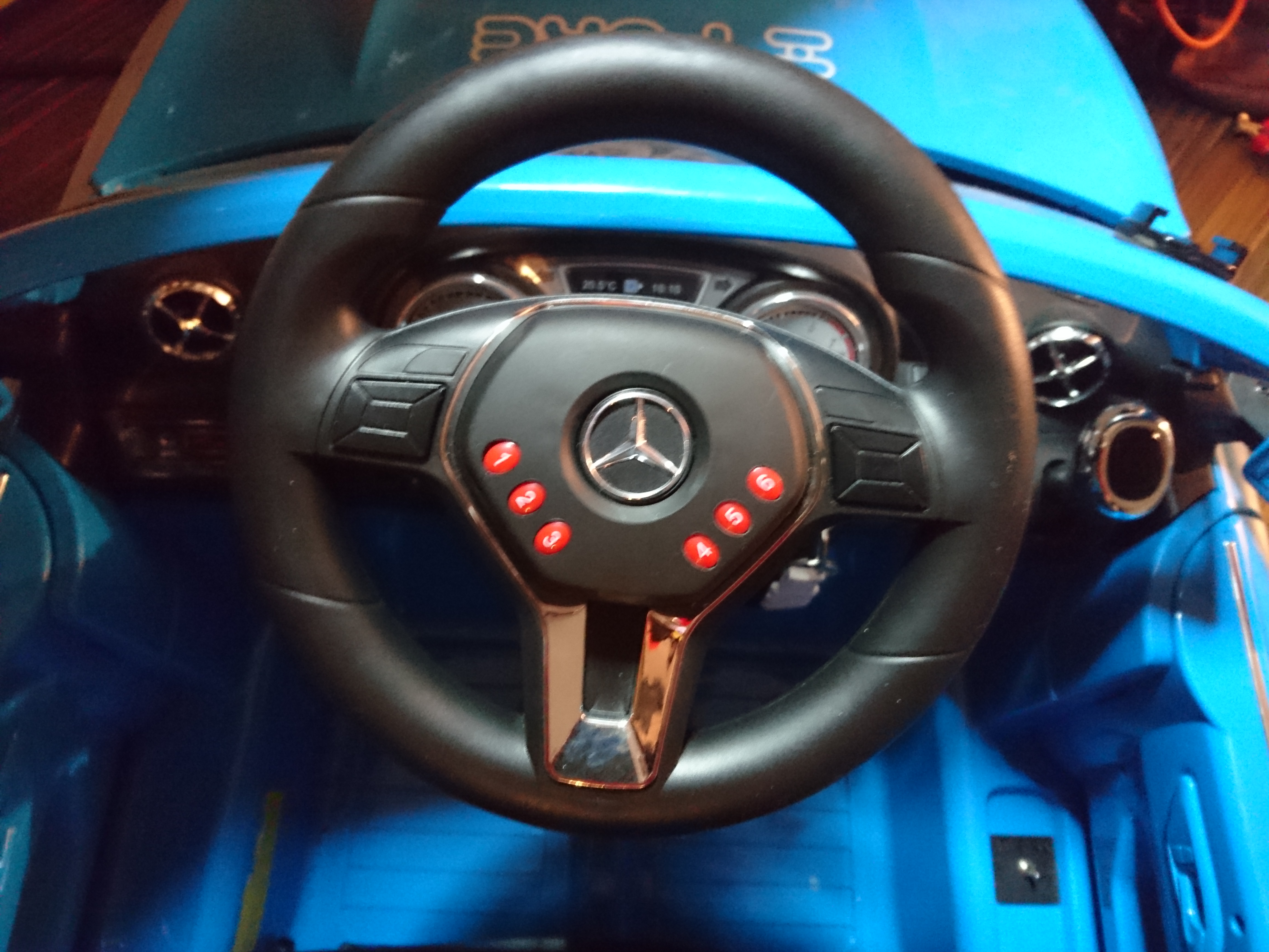
Adding the ugly keypad on the dash would have been a five minute job, but as I mentioned I want a stereo in it at some point and space is of the essence.
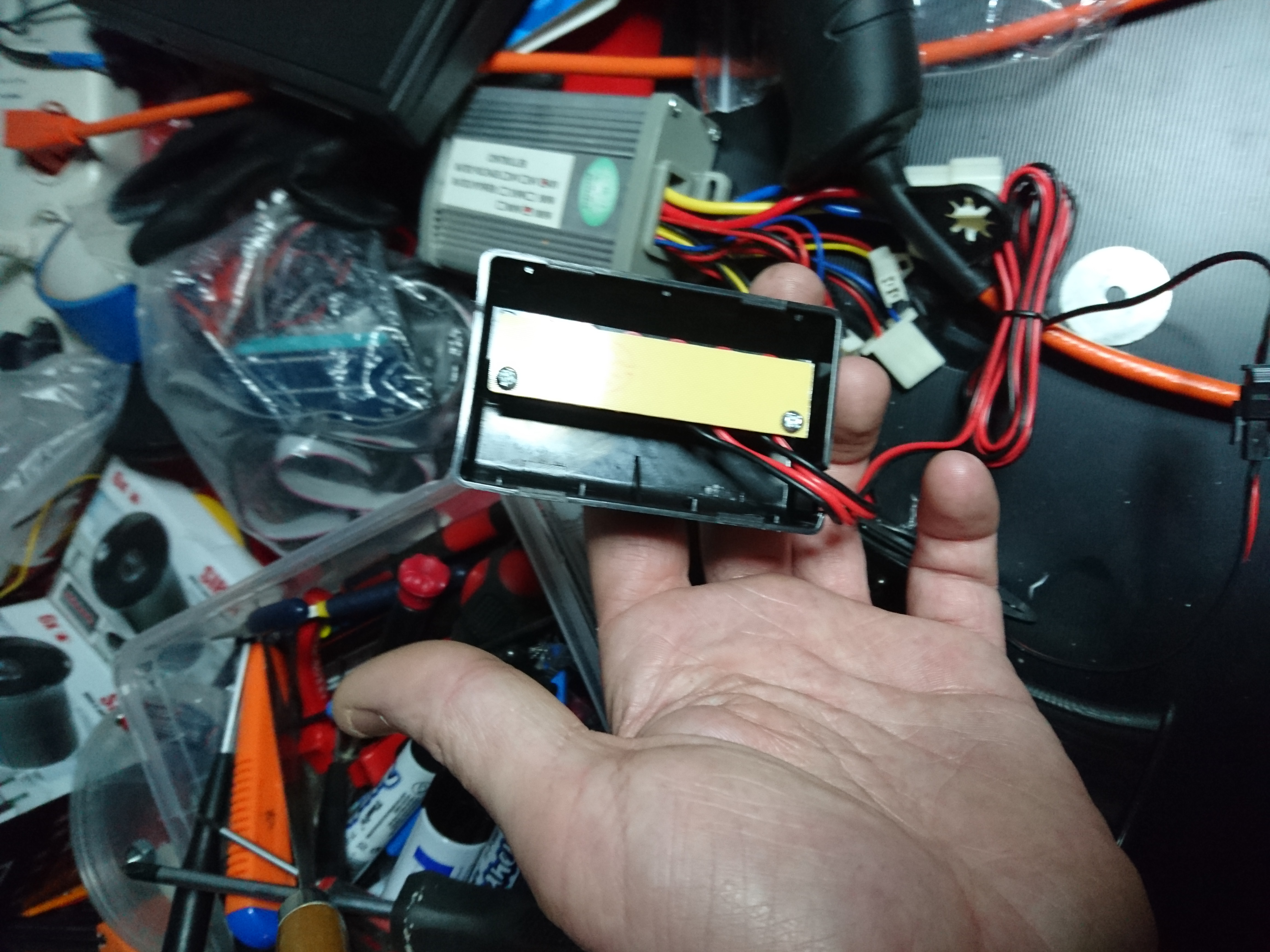
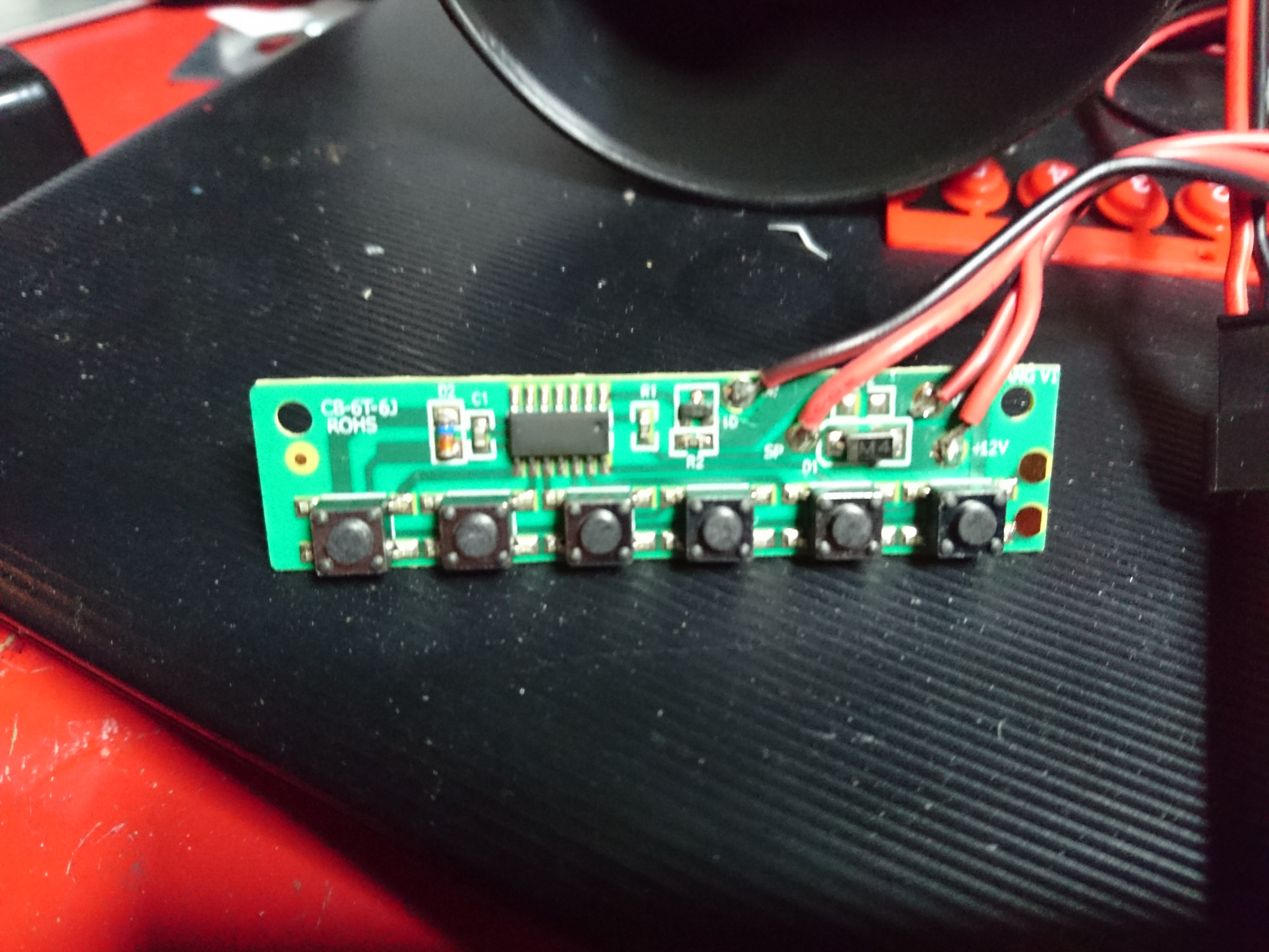
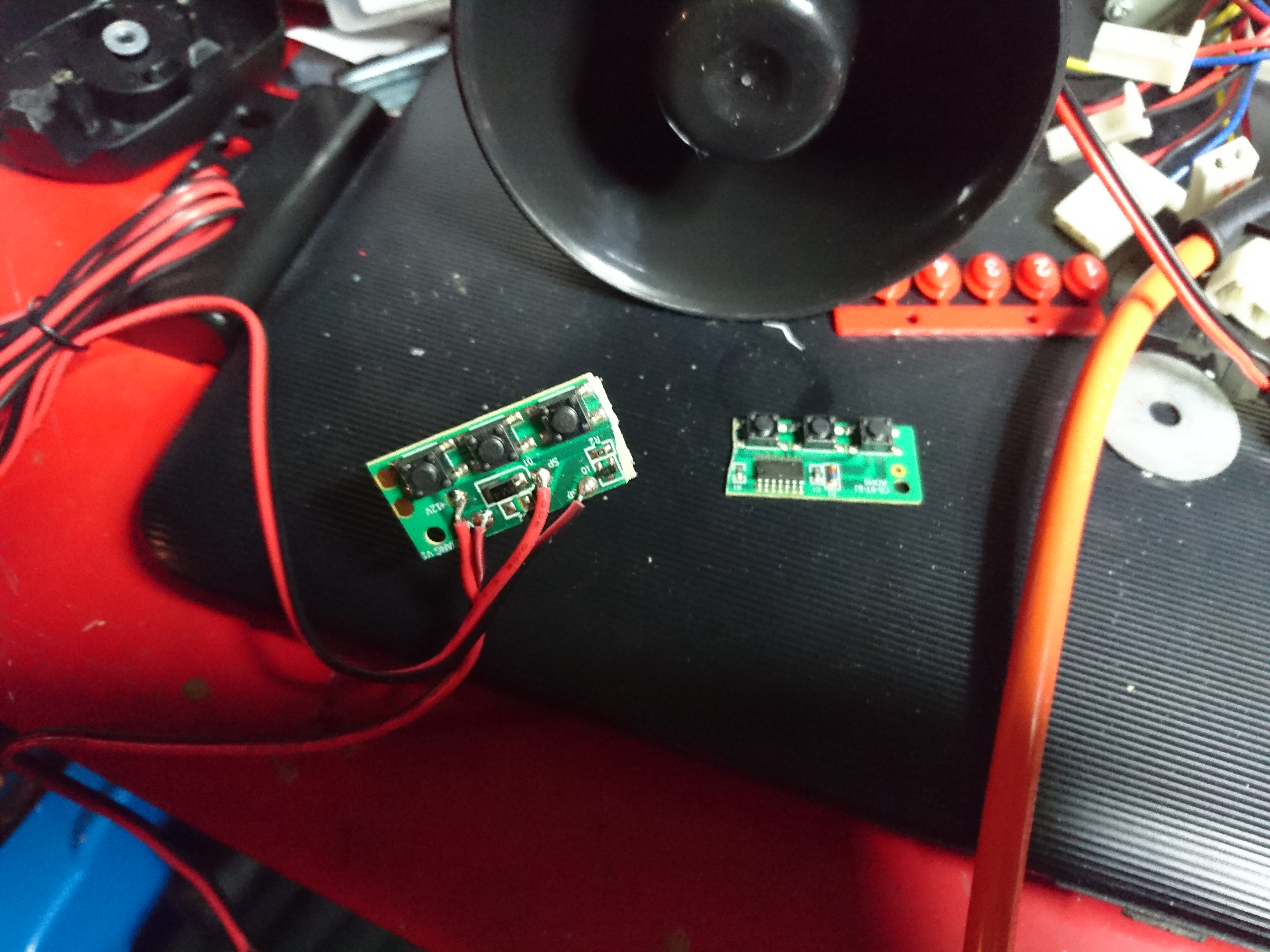
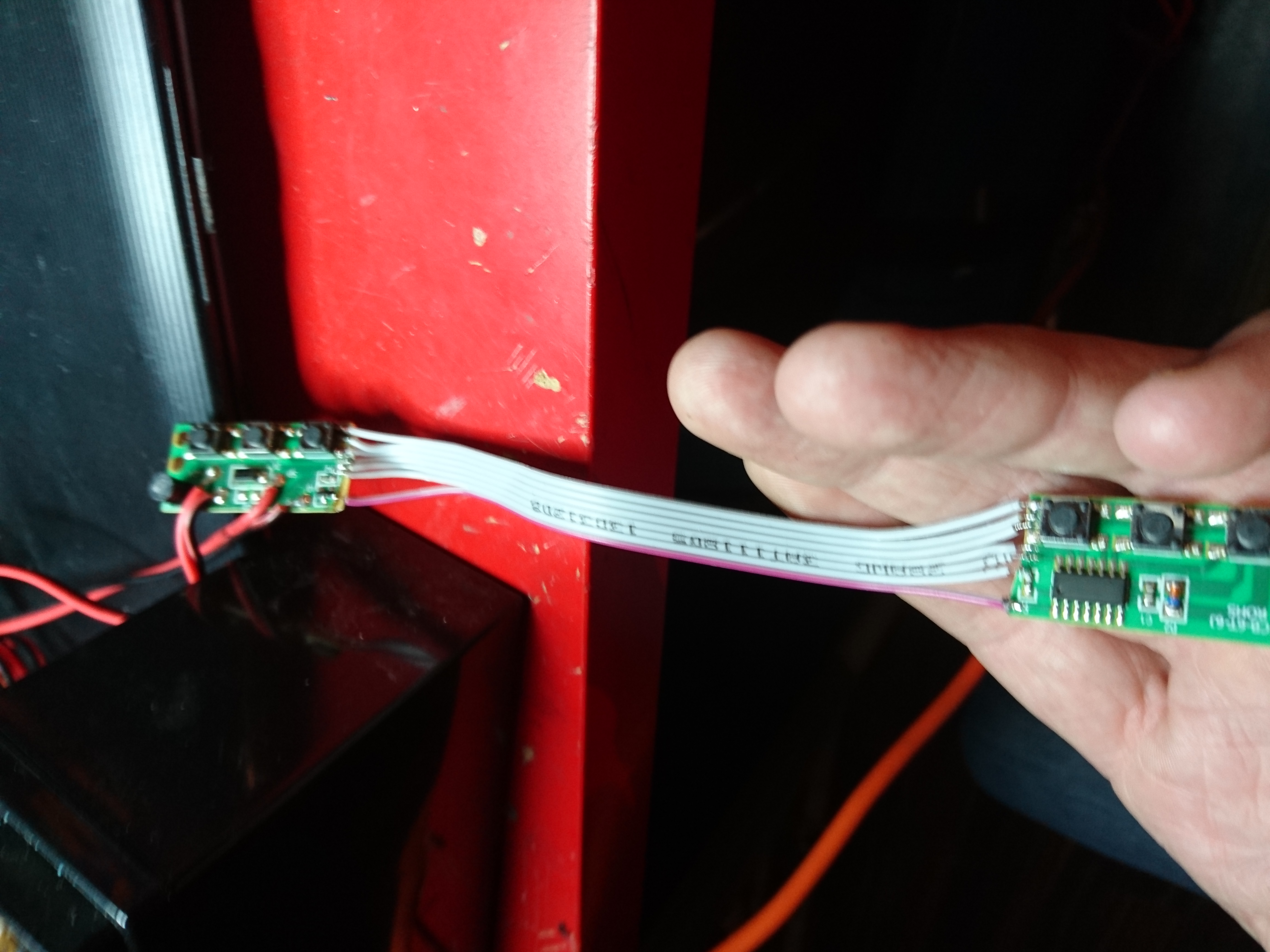
Inside the keypad is a tiny circuit-board that I could make fit inside the steering-wheel, but to fit the center the steering-wheel, it will need to be chopped up.
The best part about cheap electronic tends to be single sided circuit-boards which allow you to customize them very simply. I locate the place that has most free space around components.
After doing some measurements and make sure it will work I use a hobby-knife to cut it in half, making sure I leave enough copper trace to solder cables on to reconnect the half's.
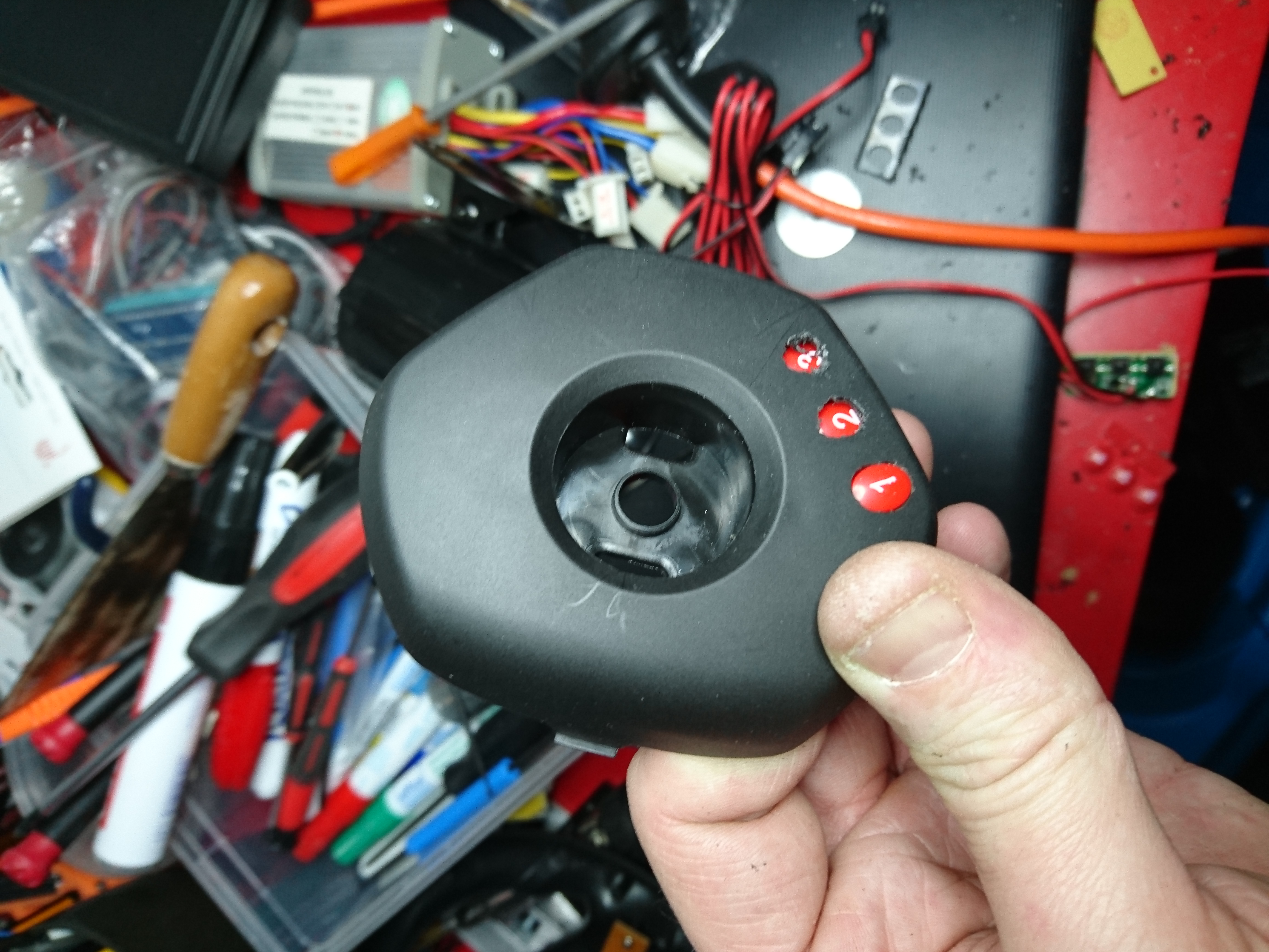
Next I make a few pilot-holes and start the painstaking process of filing away on the plastic. Not scratching it in the process is an art I still don't master.
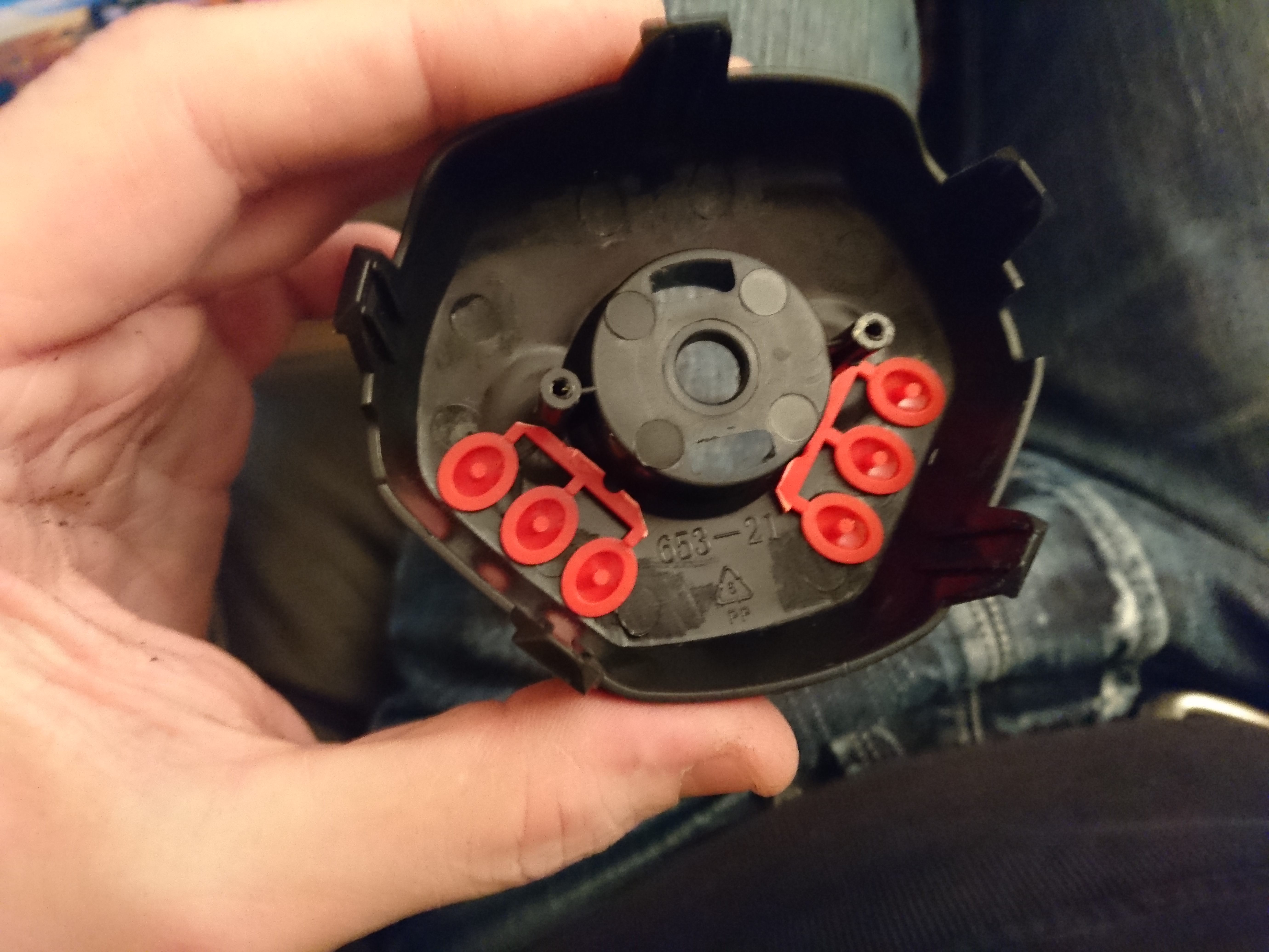
The buttons needs to be trimmed down to fit the housing too. Two component glue fixes them in their position and make sure they spring back out again.
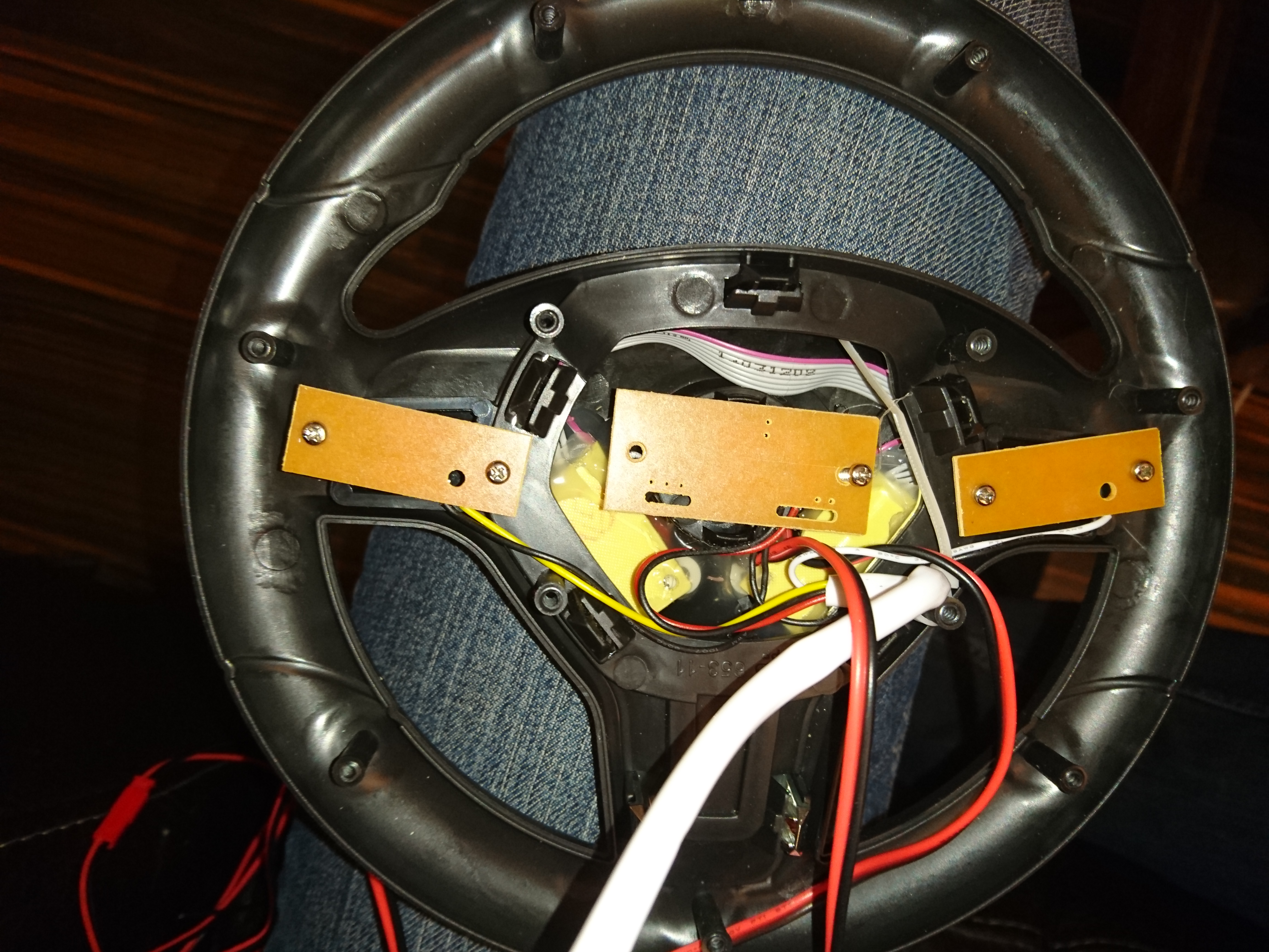
Once everything seems to fall in place I go ahead and solder it. Leaving this part for the end is critical as you are very likely to pull one of these tiny 14 solder-points and the copper it's attached to if the cable snags later. I secure the ribbon cable with melt-glue to allow me to to be less careful when putting it all together again. The circuit board is screwed back in to new mount-points I took from the old casing, and the whole construction is secured in several layers of melt glue to make sure it can handle hard pushes without breaking of.
Now all the old electronics is mounted back into the steering-wheel.
Cable is threaded through the steering column, and the wheel is re-attached.
The motors!
Engines run in a serial connected fashion, but I hear people on the web slapping both one and two extra batteries on these motors, so with the new fat battery I decided I could afford to parallel-connect them instead.
I have two blocks like this. This one parallel connect the engines and the other serial-connects them, if I ever want to return it to that configuration.
Disaster strikes!
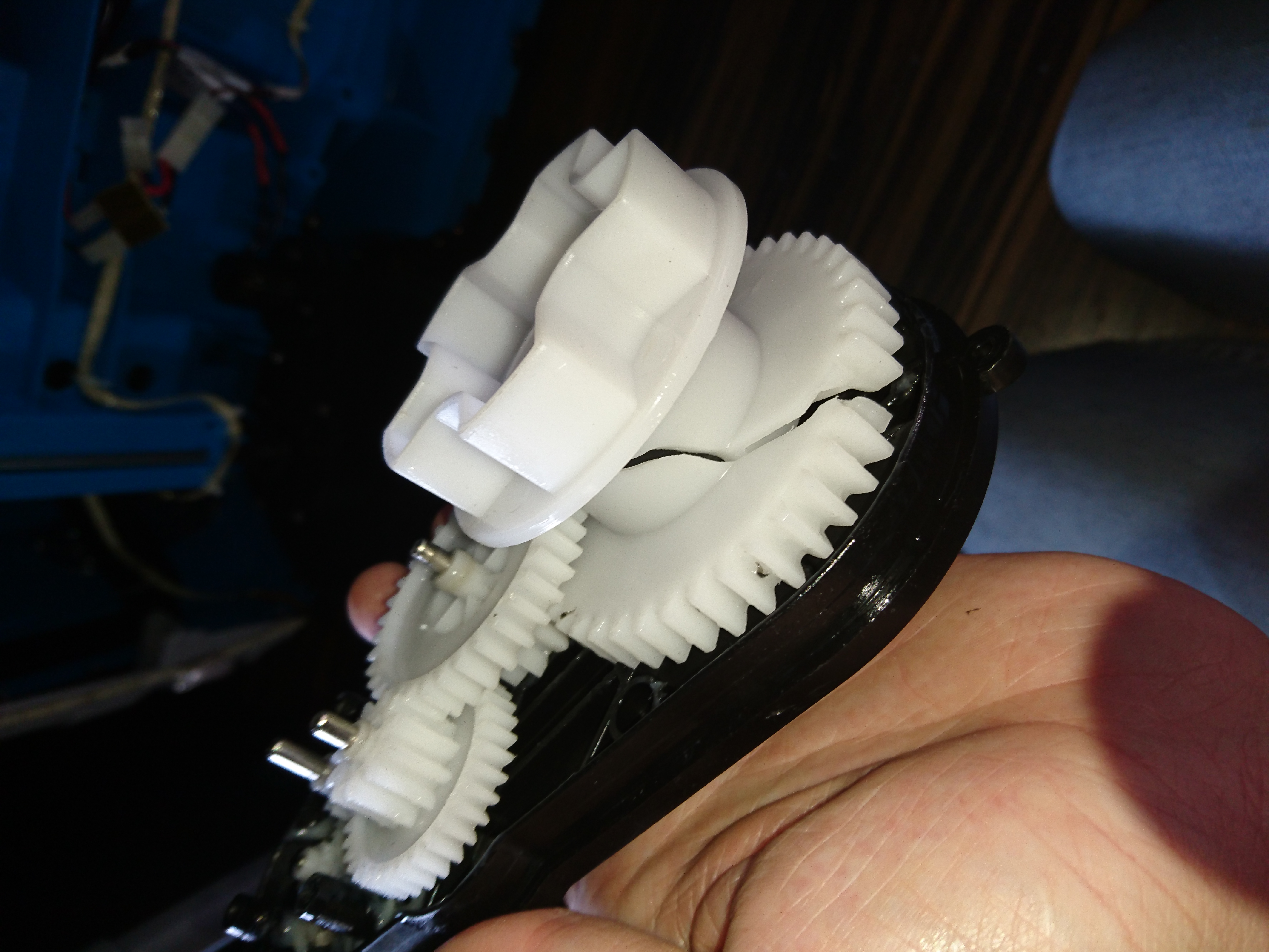
Unfortunately 12 volt, over a 40Amp ESC on a 12ah battery on the RS-390's was I bit too much for the original design to deal with and one of the gearboxes tossed in the towel.
The accident struck as I was taking it for a test ride on the street by simply reversing the car and hitting full throttle.
I never expected the main cog to crack like this, maybe some of the smaller ones but not the largest..
This made me give up all hope on using those gearboxes for any larger or more powerful type 380/390 motors. I need something a bit beefier for transmission, or it will crumble just like this did very fast.
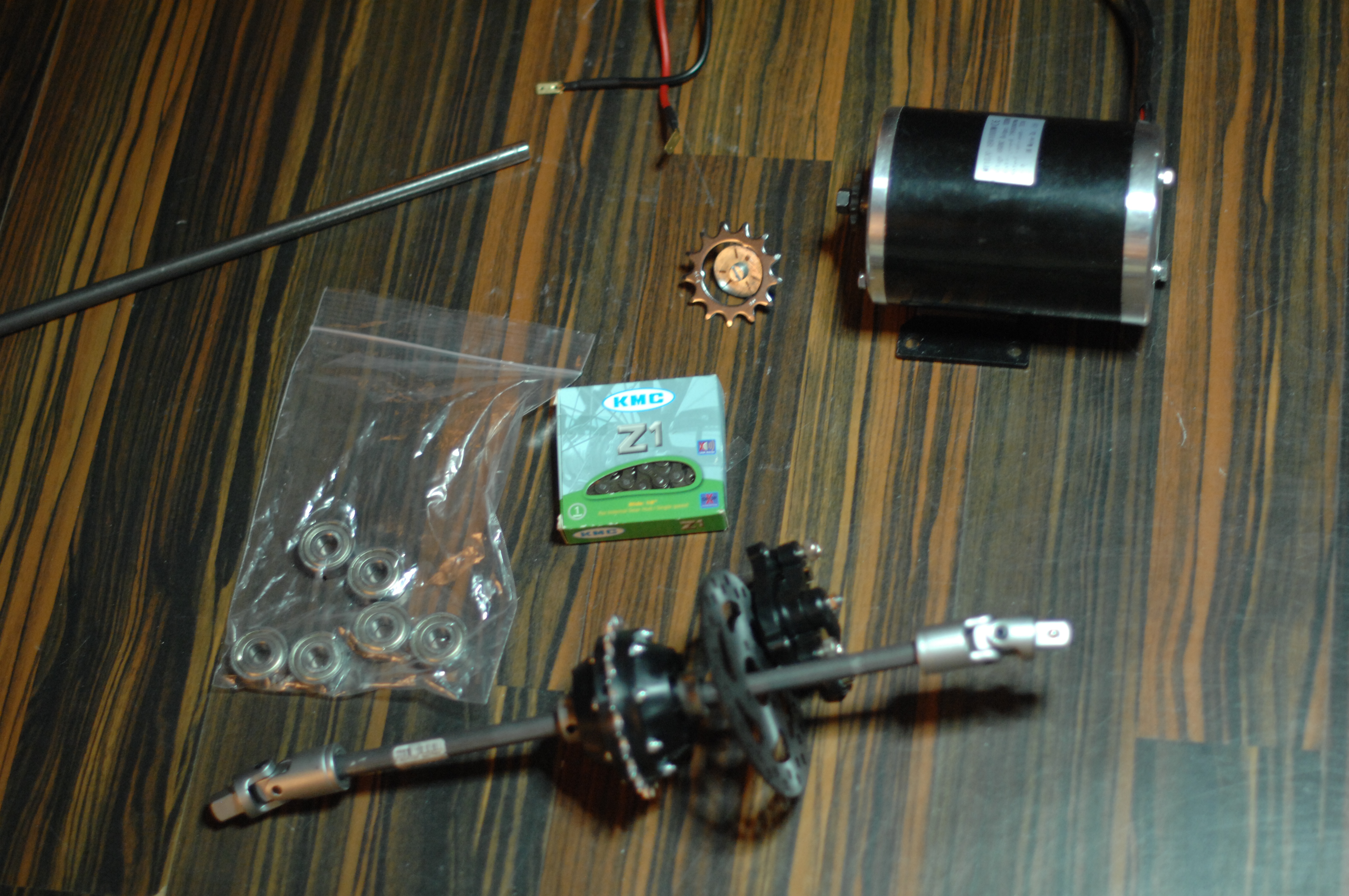
A new dawn I went above and beyond the original motors when I bought a 48 volt 1000 watt motor of amazon. The motor is meant for a e-scooter and is 200 times stronger than the original engine so a frame will have to be built. I will follow the same practices you would if building a car. If possible with individual suspension and a rear differential to make sure it corners nice. The base will be widened about 100mm and lowered about 30mm to allow it to sit better on the ground.
Material is slowly collected, the engine, cardans and a rear differential has arrived, I am still waiting for the front disk-brakes and 40kg servos.
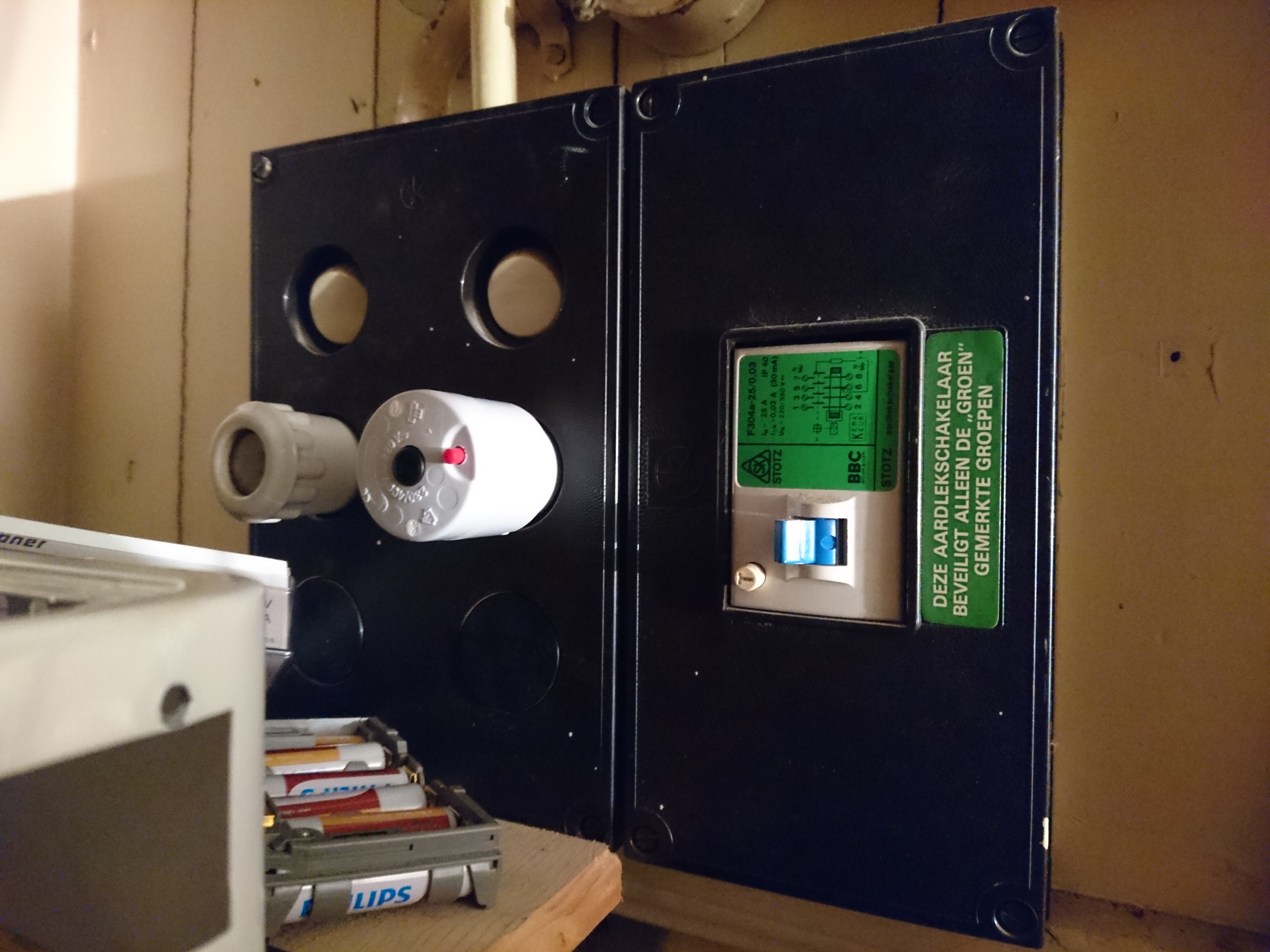
I also decided this build will need welding. For material I wish I could go aluminum but a lot of people keep advising against it, and my Argon gas is delayed 2 weeks, meaning I might for steel wishbones. I ordered a 200Amp TIG/MMA welding machine which should allow me to weld both stainless and carbon'ed steels. Additionally I had to rebuilt the main fuse-box in my house to be able to run it without burning my house down. As soon as my gas arrives I can start climbing that hill.
In the next part I will get a rear differential, suspension built and the motor mounted.
Suggestions and inspiration is very welcome. Current challenges:
I need wheels and have been looking for weeks with little avail.. They should be 300mm diameter, ~120mm wide, preferably with an aluminium hub and air-filled tires for weight-reduction. Any suggestions are welcome. I currently explored Golfcaddy's, wheelbarrow, go karts and ATV/Quad.
Suspension. Should be 70mm(compressed)-125mm(decompressed) long and deal with 25kg each.
2017 has been super eventful year for me, not leaving much time to write here. As usual, work dominated most of my time and I added quite a few products to my CV.
Most importantly this year: I had a son, which in terms will be my biggest and most important programming project many years to come. Needless to say a lot of the hacks now aims at toys intended for him.
I attended SHA2017, where I started playing with PyQT5, went to a range of good talks which sparked interests in a bunch of new concepts like machine learning, that I am looking into more in 2018.
I bought a Kossel mini 3dprinter which I systematically broke every part on, redesigned and rebuilt. Once I am done upgrading the 3d printer, I decided I will build a 3d scanner too, so stay tuned.
I revamp the complete cooling system of my Honda CBR1000RR, crashed my Kawasaki Ninja 636, broke my hand, hacked the cast, ABS welded the fairing of the bike together again.
With all this 2017 have been packed with things to write about and the coming days I will start writing about these projects.
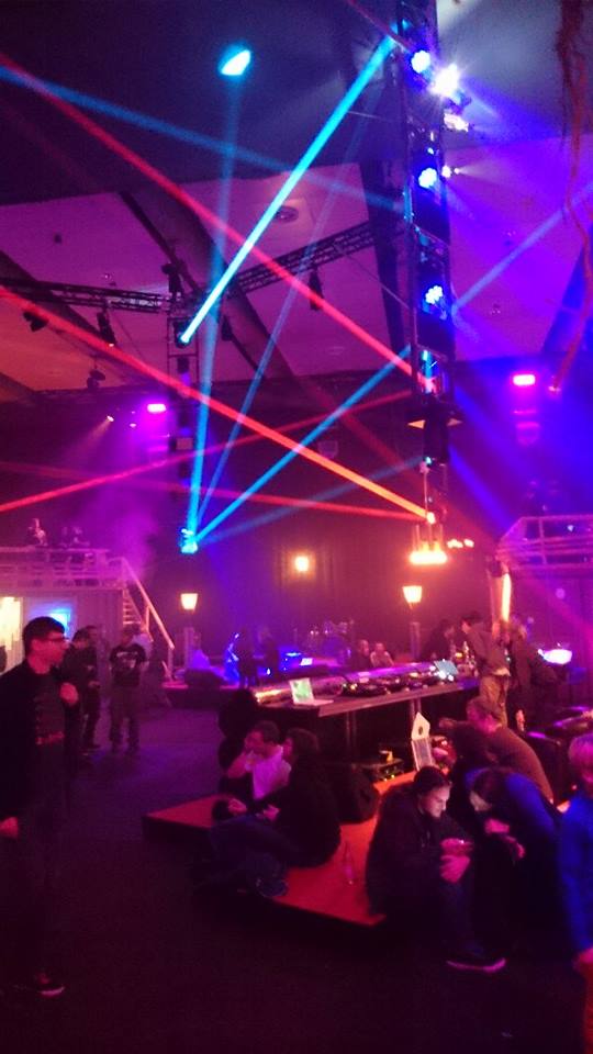
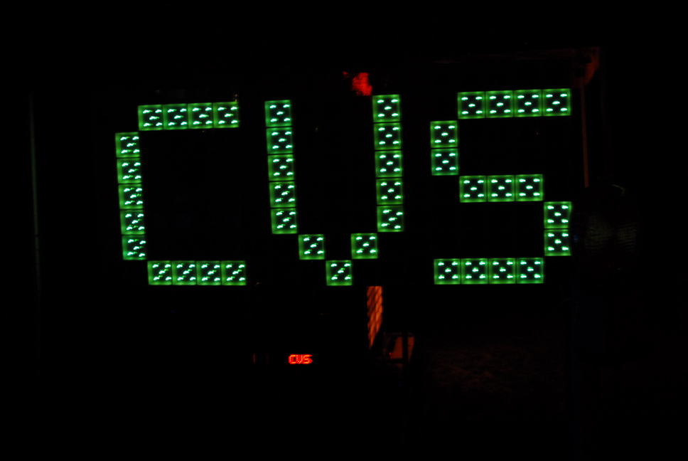
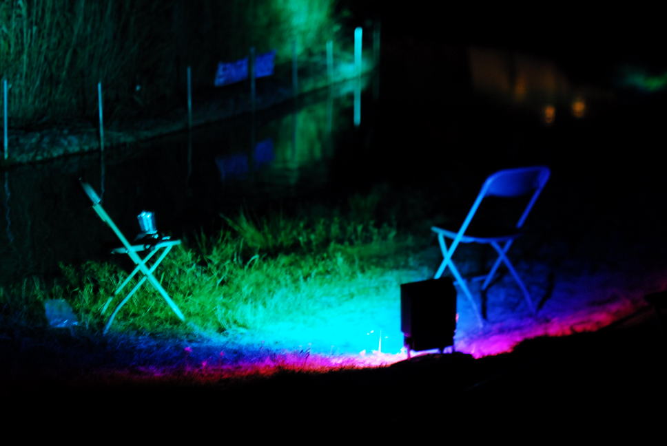
The camp took place from 4 to 8 August on a scouts terrain in Zeewolde. At least 3300 hackers and technology minded people from 50 countries participated in workshops and discussions.
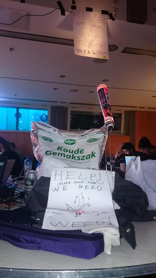
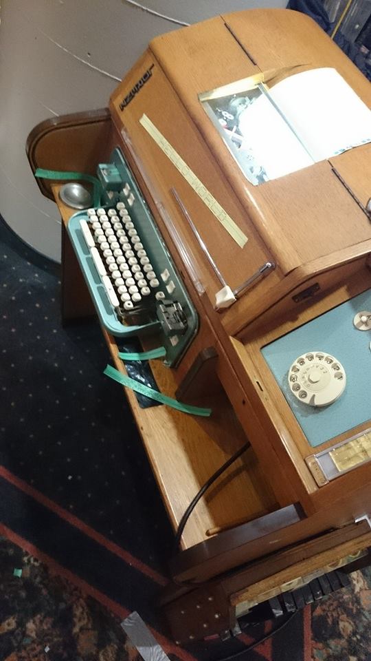
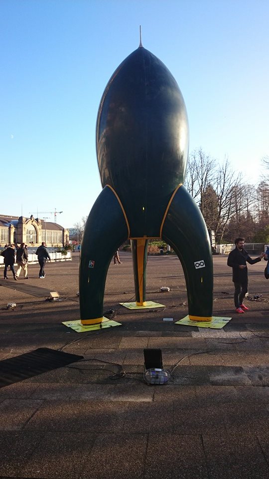
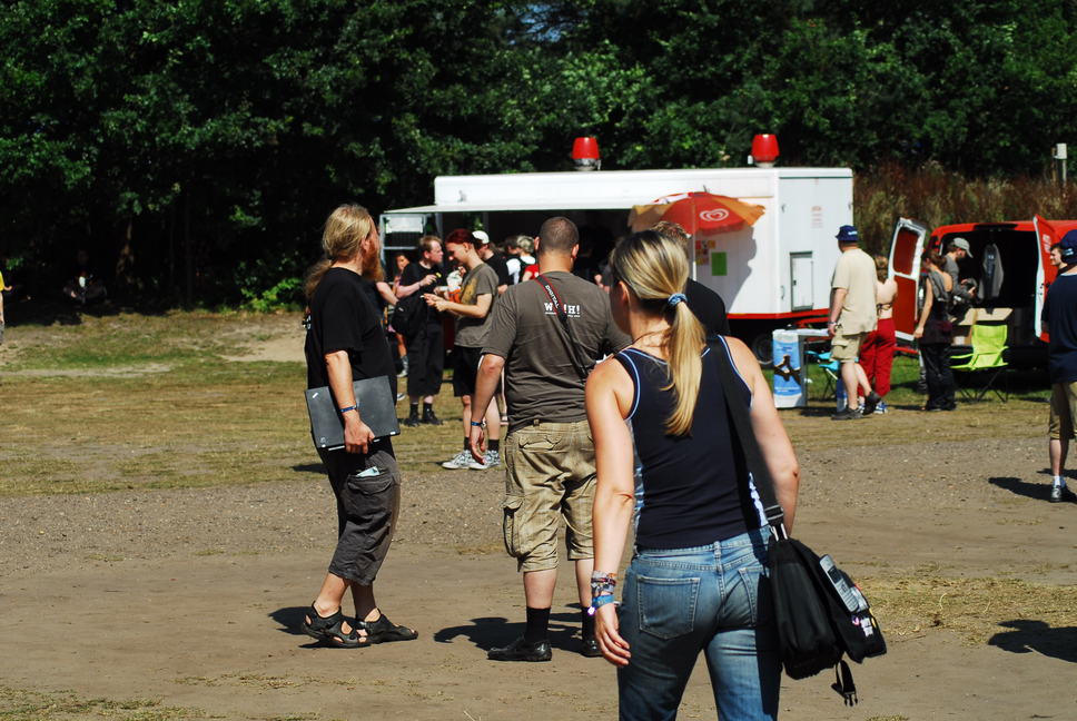
Retro-posting this 10 years later, but it should have been here all the time as it truely belong here and the blog was already up and running. Just some random pictures from a great congress.
In a sense this entry doesn't really belong at this blog as no actual hacking was ever needed so I am sharing this as more of a security advisory for someone that never decommission a server.
After a wet night in the bar with the guys I found a computer sticking out of a waste container on my way home. I noticed the IBM X-series logo which made me disregard that it was covered in an inch of snow and I dragged it home.
It turned out to be a X3200 tower, running a Xeon E3400 cpu at 1.8 ghz, 4 gb of ddr2 memory, 2 sata-mirrors.
80gb for OS, one 500gb mirror for data, by the look of it.
The hardware
After a proper drying I plugged it in. Power icon was blinking green but pushing the button did nothing.
I measured the button using a multimeter, but the switch itself worked. I found a "Power On" jumper on the motherboard and once shorted the machine rev'ed up its fans but never let ACPI kick in to lower the RPM of the fans, nor initiating BIOS. Monitor indicated no VGA signal either.
I was fiddling with jumpers for quite some time, I reset the CMOS and noticed that when I moved back the jumper to Disabled that the box twitched to life. The monitor flickered up and the blue iconic X-series logo filled the screen, with a few beeps and warnings about the CMOS battery having low voltage it came back to life. Unfortunately I had no disk connected to the system at this point and it would take another 45 minutes before I succeeded to do it again. After hours of trying to streamline the process of getting it booted the recipe for success seems to be:
Use the Power ON jumper for 20 seconds. Pull the power-cord to the server. Enable CMOS-reset with the jumper on the motherboard. Put the power-cord back in. Leave the server for 20 minutes with the CMOS-reset ON.
Then.... pull out the CMOS reset jumper :) BOOM! The server boots Windows 2003: A real man-OS!
Not being a huge fan of spending 20 minutes on booting any machine I kept looking for something simpler.
Trickling pin 2 and 3 on the WOL-connector on the network adapter did make the power-led on the motherboard flicker but once more didn't start the machine up.
I never mentioned how restless I am as a person in this blog, but for people who know me that is a fact.
What I did mention was that both OS and Data disks where both in a mirrored configuration, once this was confirmed in the BIOS, it allowed me to snatch one disk of each mirror to be able to see what was lurking on the sectors while waiting for the server to get ready for it's next boot.
"This is Windows.. I know windows!"
I hooked up the OS-drive with a SATA-to-USB-dongle and mounted the NTFS partition on my linux-laptop.
The 80gb drive was divided into 2 partitions. 21gb for OS and a 55gb labeled EXCHANGE. I was happy to see no attempt at encrypting (or destroying the drives for that matter) were made but I guess if I saw such attempts I would be even more curios to see what they tried to hide from me. I am far from an expert on Windows these days but it didn't take long to locate the the email data-directory belonging to the email exchange server, that the partion-name indicated would be there.
TIL that e-mails are stored in clear-text in Exchange 2010.
Curious about who owned the machine before me I started reading mail after mail. A picture slowly dawned on me.
Some kind of medical related, pedicure, new age thing, something? I was intrigued.
Using standard un*x tools like cat, grep and more I could see every email sent and received from 2007 to 2011.
Just for the fuck of it I greped out 20 lines surrounding the word "Password" and "Wachtwoord" and piped it to two files.
Now, I understand a tiny non-IT company can mess up and send out clear-text password..
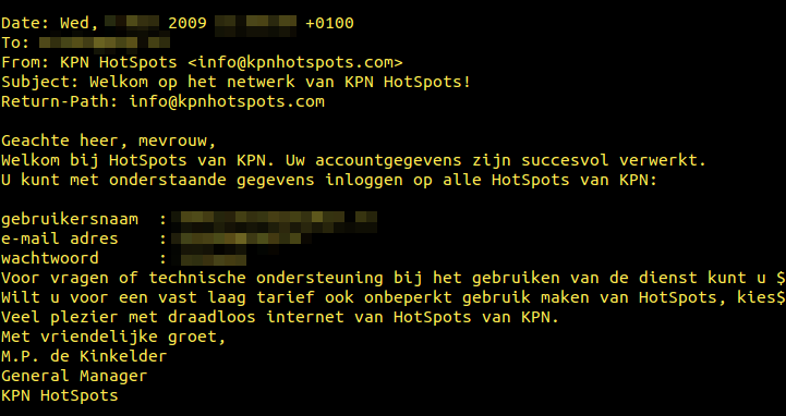
..but KPN is the stately owned phone-company in Holland, and should know better :)
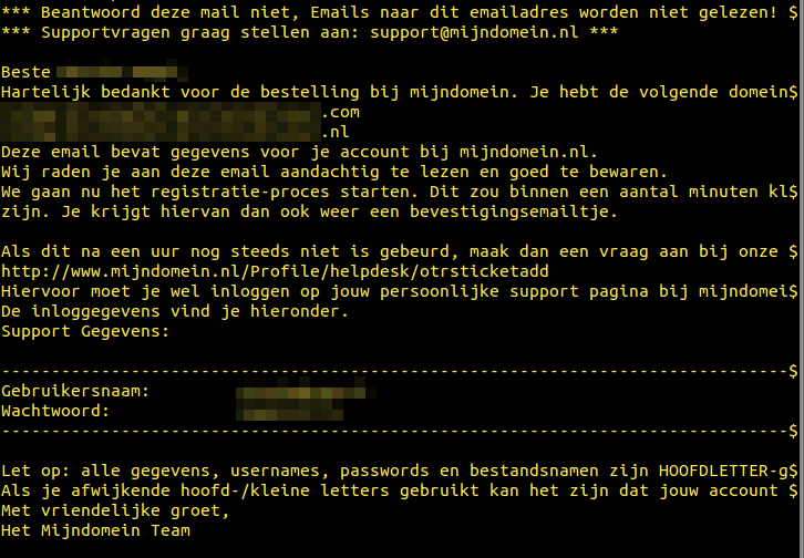
Hosting companies don't seem to mind keeping it simple.
I guess it's up to their customer not to keep the same 6 character-passwords year after year. I am however convinced mijndomain.nl has changed practices on this topic anno 2015?
I want to point out that I never tried to use any of the passwords to verify if they worked or not as that would be highly illegal. Additionally some logins were to patient care systems, making it utterly unethical to touch. I did however google the companies, visited their homepages to get a greater idea of exactly what they did and how they connected to the company who's server I stumbled into. Needless to say I read up on the company itself, which still exists.
Seeing many passwords never changed during the years and many were frequently reused between different systems, I feel safe to bet some of them still work. But I wasn't really that curious about the passwords and continue exploring the rest of the emails. Who were these guys?
Slowly the picture of the prior residents cleared. They had their own little newsletter, were selling subscriptions, seemed to be holding courses, involved in Integrative medicine (Never heard of it before but I am a skeptic. A fast search through all mailboxes got me bored. Almost all of the emails in all the email-boxes was work-related, how boring of them. You can only read so many of someones emails before you need to do something else.
I started checking out the Data drive. It turns out this was not only the Exchange server in their tiny infrastructure. It also carried their Domain controller and roaming home folders. I searched the user home folders, starting with the Administrator account. I could not believe my eyes..
Someone already brute-forced the server and the result files were still there :)
3200.passwords
Worth to mention is that it took 7m24s to brute-force the computer-knowing layout guy's password, while it took 2h35m35s to crack he person I assume works in accounting.
Almost all passwords followed the same standard: X123Y4, where _123_4 never changes between users and the letters did to a certain degree. I can only assume these passwords were set by whomever delivered the system and never changed.
One user seemed to have changed his password but instead of setting a better password he went with a 4 digit only password, which was cracked in 26 seconds.
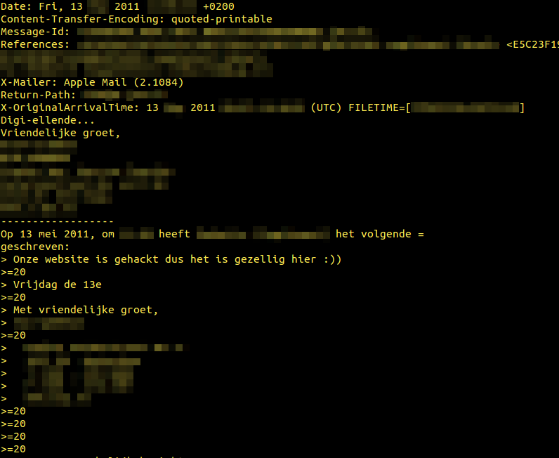
Initially I assumed it was the Administrator's own pen-tests but looking through the mail again, it seemed they had been hacked around the same time this password file was created:
One guy seem to enjoy the peace it brought to the office and point out that it is Friday the 13th. Some external partner responds "Digi-missery".
In the meantime the server booted up again
The server was finally booting up on two single disk mirrors. My eyes glittered in the LCD-light. I would finally get to hack something.. or.. well.. I had the passwords to all accounts already, so technically still no hacking. But I would at least get to enter a username and password and feel like a hacker. Nope, machine seemed to have a registry hack and automatically logged in as Administrator, but something hung it after that. As I didn't want it to start connecting out on the internet I just hooked it in to a switch without uplink.
I have to say I was a bit surprised to find the brute-forced password file, but not as surprised as I was about to become. Turn out this machine also hosted several windows shares.
One was most likely used by their HR, as I could find ALL information about people working there, like digital copies of their contracts and dismissals.
Another share contained a lot of access databases. Their complete customer-database, sales records, lists of prospect customers and tons of PDF-material about their products.
With the data I had at this point, I could map the whole company up on a time-line, seeing who started when, what they got paid, when they left. I could build a visual picture of who emailed who, which seller caught the big fish and who was just complaining about work while slacking. With almost 10GB of email, 500GB of data and no real idea of where I wanted to go out of it, this blog-post got hanging mid-air. It would take a year to go through it all. And most of it way to fucking boring to plow through.
I kept looking and found pictures from a few events their company participated in. Some of the pictures were named after who they depicted, allowing me to put a face on most of the names from emails I had been reading. It almost felt like I knew the people at this point. I was about to get way closer than I wished for.
I explored the the data-drive and found a backup windows share. Turns out this server was also used by some of the people to back up their laptops, and some of them were very.. blunt.
One of the sales guys, which I recognized from pictures I found from a kickoff he went to was obviously gay. I don't claim to be able to spot a gay guy, nor do I judge anyone being gay but this guy had tons of pictures of him and a friend fucking a tiny Asian man making me pretty sure this was the case with this guy. Among the data he traveled with (and cared enough to backup) was GB's off piss-porn.
I wanted to finish up this post a while back, but as I mentioned, I had NO IDEA of what to do with this. Obviously I would never attempt to use it against the company or any of their employees, but the next guy to find this might not be as friendly as I am.
Bits of advise, anyone?
No matter what you Think is on a computer you are getting rid off, small pieces of your life's puzzle are stored on that machine. May it be in your internet-cache, in your cookies or from RAM in a swapfile. Someone with the right motivation or amount of interest will be able to scavenge it and use it against you.
If you ever toss away anything with a NAND-circuit (like a broken cellphone that contained naked pictures of your gf), unscrew/drill out the screws and use the a car battery charge to short every circuit on the board, making sure who ever tries to retrieve the data, gets a run for his money.
If you ever toss a PC with a harddrive, remove the drive, smash it to pieces with a hammer or drill right through it a few time. It only takes a few minutes, and you know for sure you are safe from 99.9% of people as curious as me.
If you are decommissioning a combined mail-server, file-server, piss-porn-repository, containing all your financial statements, all your customer information, every edge you have on your competition: For the love of Science, make sure no-one can just pick it up and just power it on.
Retro-posting this 11 years later, but it should have been here all the time as it truely belong here and the blog was already up and running. Just some random pictures from a great congress.
A good friend of me approached me 2 months back with his broken Nokia cell-phone, that all of a sudden died on him.. Number, pictures and messages were stored in the phone, leaving him without all his contacts.
I figured I could just have a look if it was something simple and if so, get it alive again to be able to back it all up. Once home I first tested a regular micro-usb cable but I did not see any led blink or indicate that charging was taking place. Measuring the battery it was totally flat but lacking means of charging it I told him that I didn't get very far. Since that the phone has been laying around, doing no good to no one.
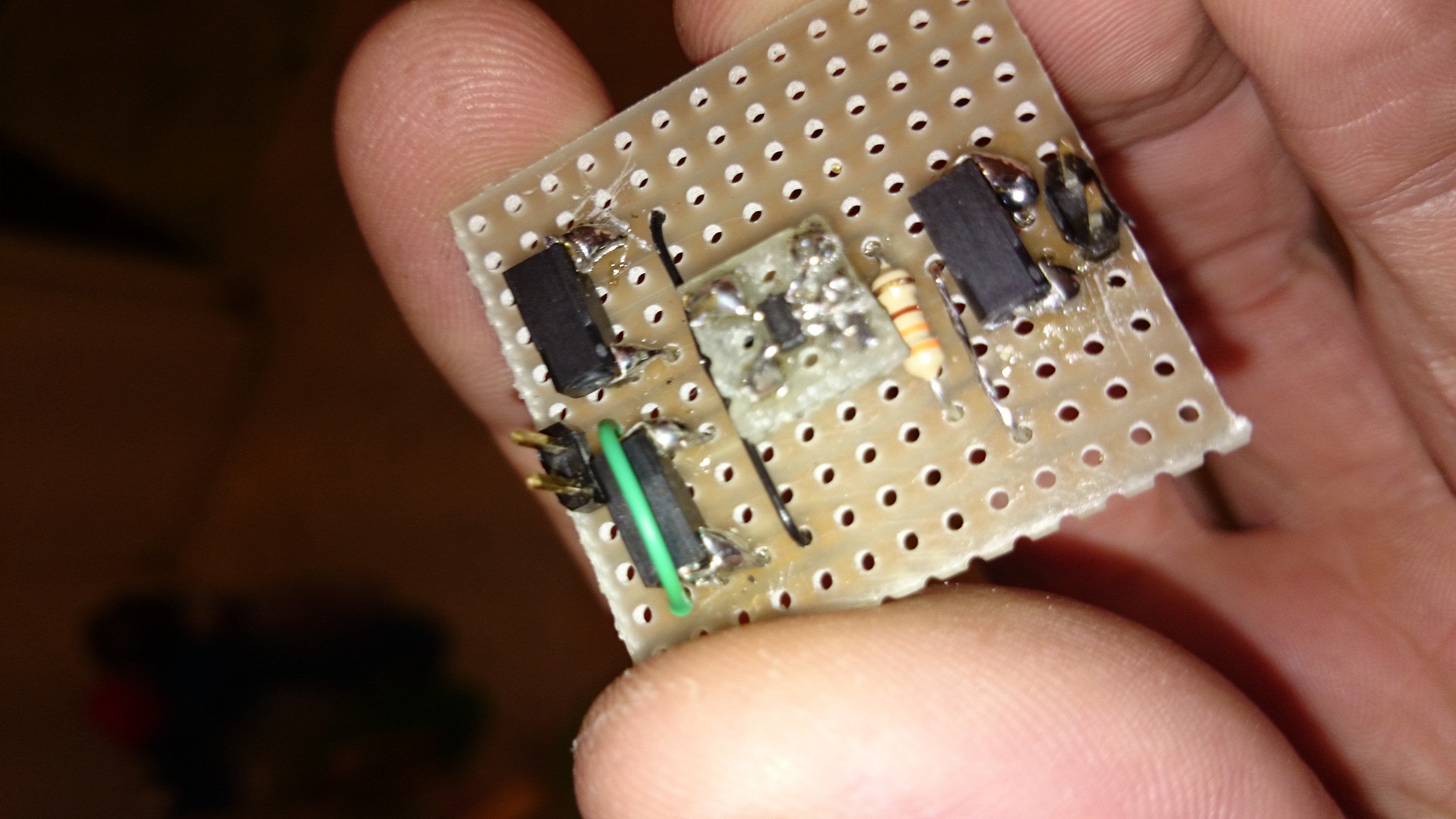
As I finished of the video camera charger the other day, I still had some max1555's li-ion charger circuits at my disposal and figured I could build a second charger and see if I could get some life in the battery circumventing the phones own charging system. Since this would not be a permanent install I figured I would build something that could be reused, that had clear test-points and that could easily be connected to whatever cell I needed to charge.
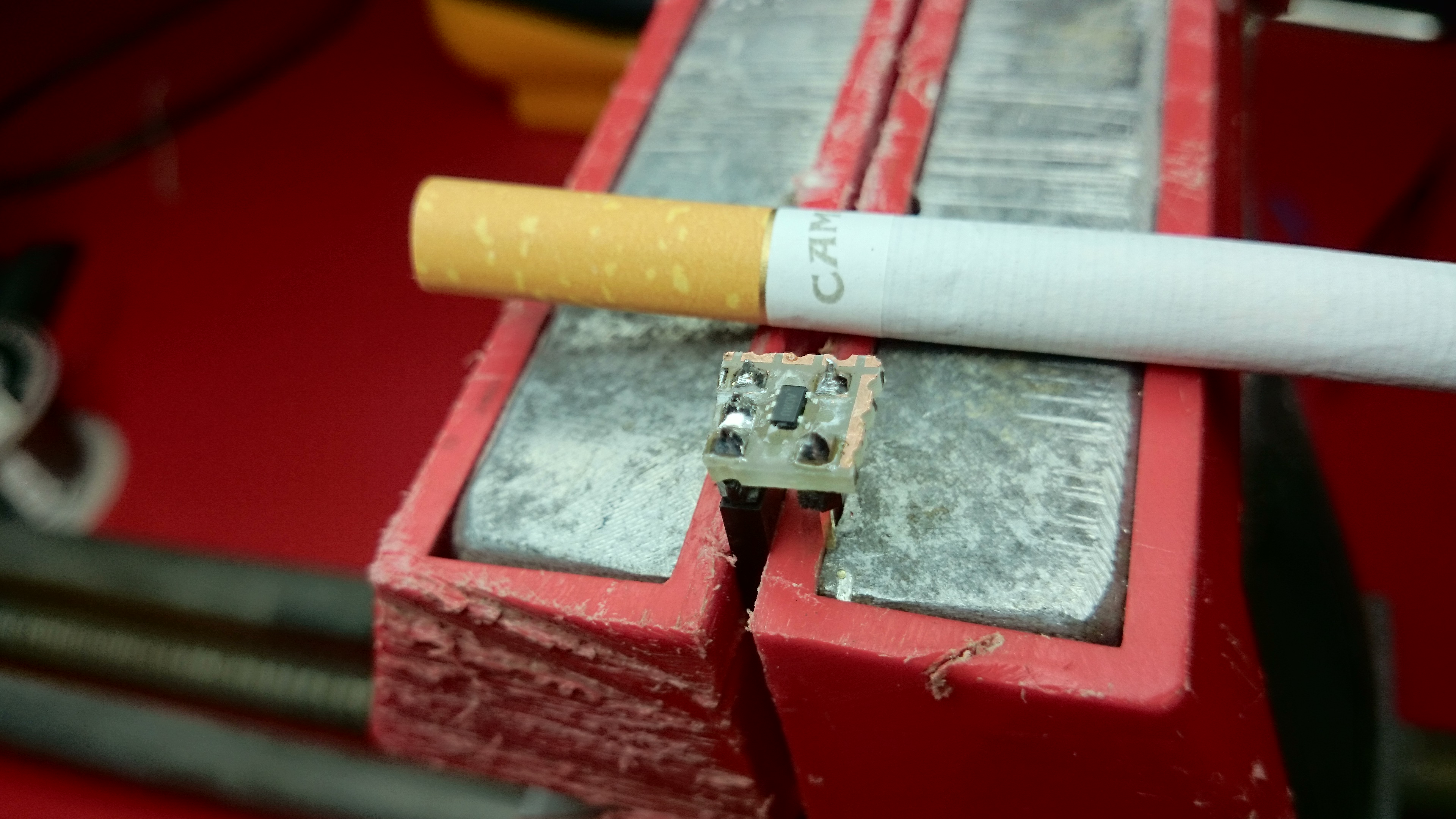
As space was not an issue I mounted the MAX1555 on a separate board (cigarette for scale, the MAX1555 is a non-smoking IC)
And then continues to lead out the tiny legs of the MAX1555 to the board. This board was added on top of the next circuit board using basically almost the same schematic as for the video-camera in the earlier article.
The battery belonging to the phone turned out not to accept charge, and in retrospect I find out the phone broke when he tried to charge it with a 220 volt charger in New York (110 volts ftw!).
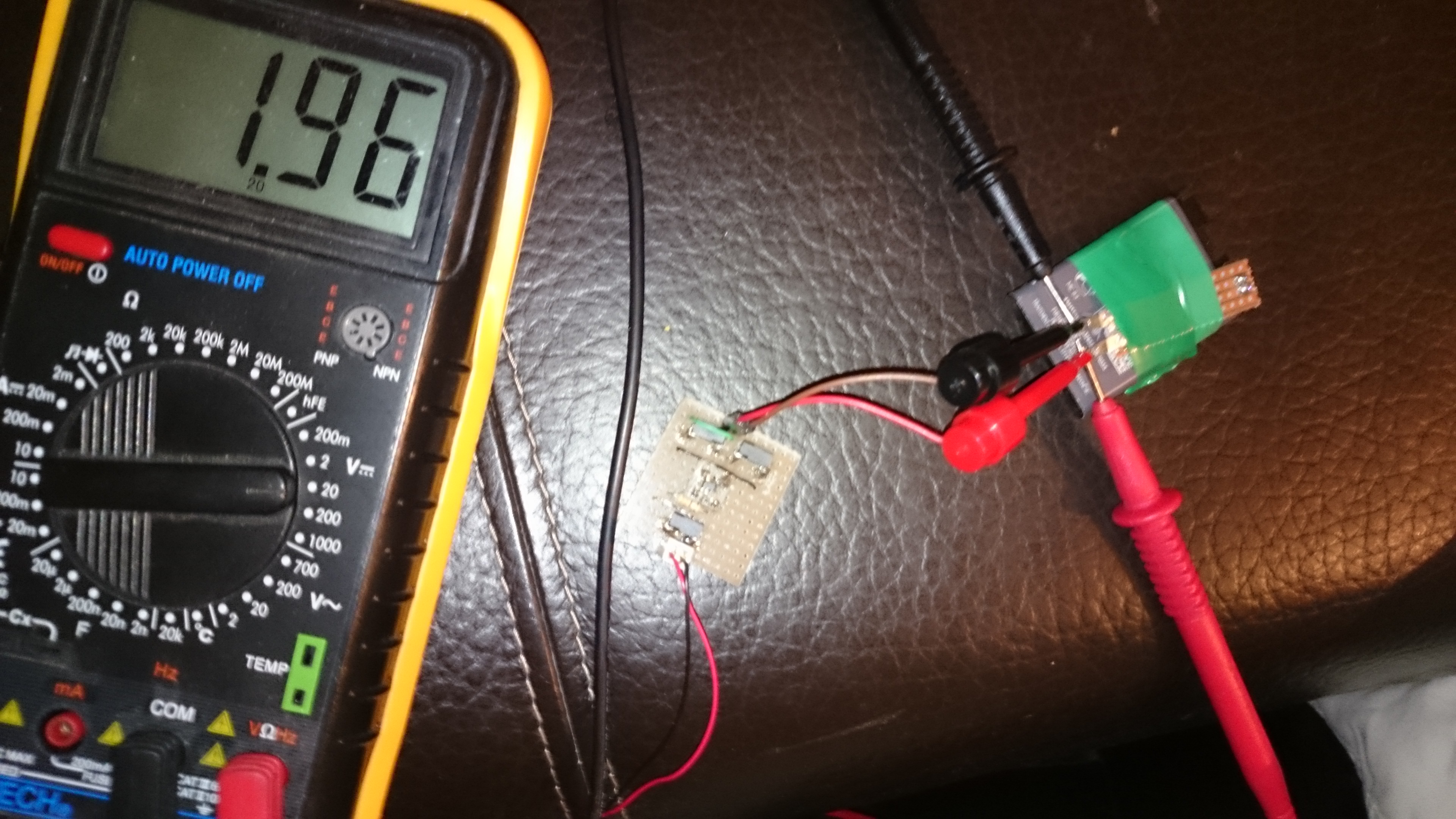
This explained a lot. I took old nokia li-ion battery, hooked up the charger and the multimeter to see that the charger was working and the cell accepted the load:
Turns out this old battery also had done it's fair share of heavy lifting, and I had to dismiss it. Next battery in line was another Nokia battery from one of it's first smart-phones. This battery worked straight off, and as I reached the magic 3.7 volts, I connected the battery to the phone and pressed the power-button, VOILA!
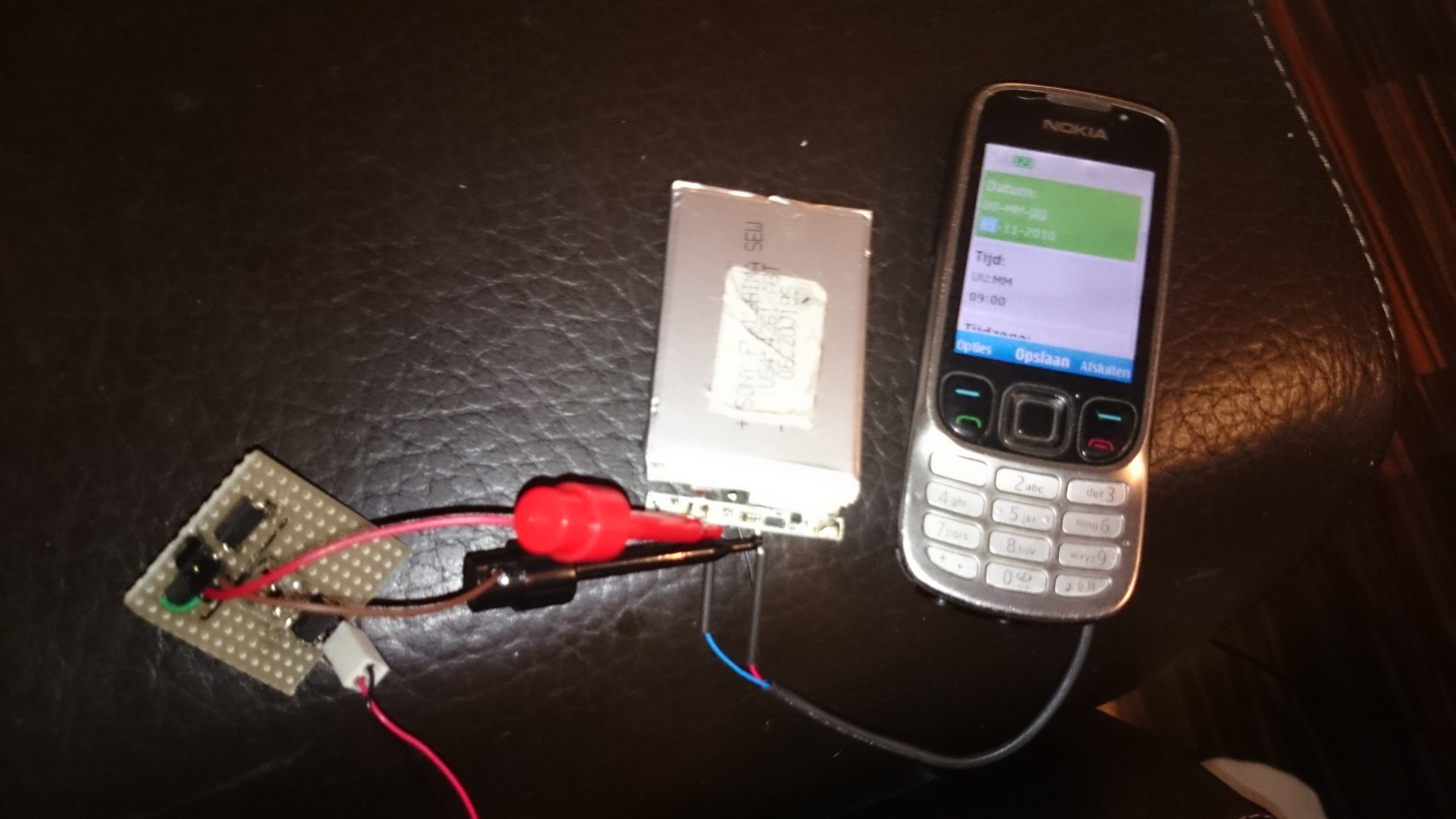
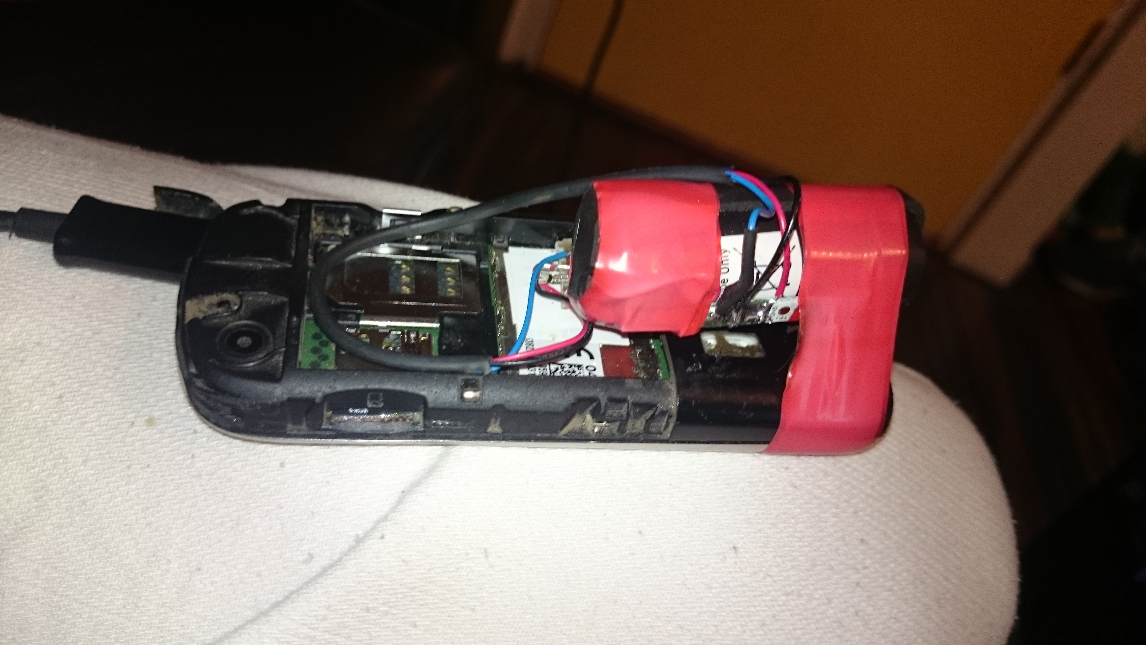
I called Mat to inform him the phone was alive again, who was very happy but this celebration lasted short, as the aluminium connector from the battery broke off, and no matter what I tried, I could not reconnect it. Having ran out of Lithium-Ion batteries I was stuck with Lithium-Polymer batteries. I desoldered the battery controller seen under the accumulator in the picture above, I soldered it to the LiPo cell instead resulting in a working but franken-phone seen here:
It's not beautiful, but it is working and all contacts and sms are once more safe. Yet another happy customer :)
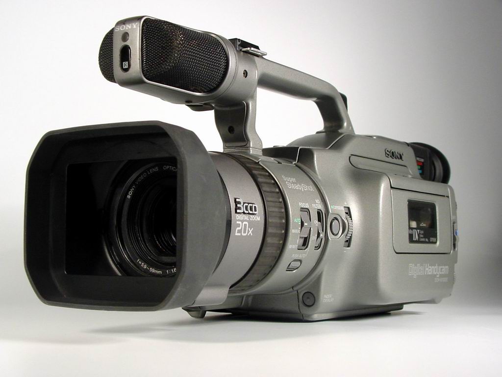
I have always loved the VX1000-series of video cameras from Sony. Released in 1995 at a price of $3500, this camera revolutionized what Sony calls the "prosumer" customer segment, being the first DV-camera using Sony 3CCD color-processing and firewire interface. To this day, the VX1000 has a huge active community and a refurbished camera can still bring up towards 800 euros, something you rarely see with 19 year old electronics.
dcr-vx1000
A friend of mine was lucky finding one of these tossed out on the streets of Amsterdam a half year back and as soon as I saw it I wanted it. It had no charger but he knew what he got his hands on and figured he could probably get it working.
Some time passed and my friend realized he would not get around to fixing it so I figured I could give it a try and bought it cheap.
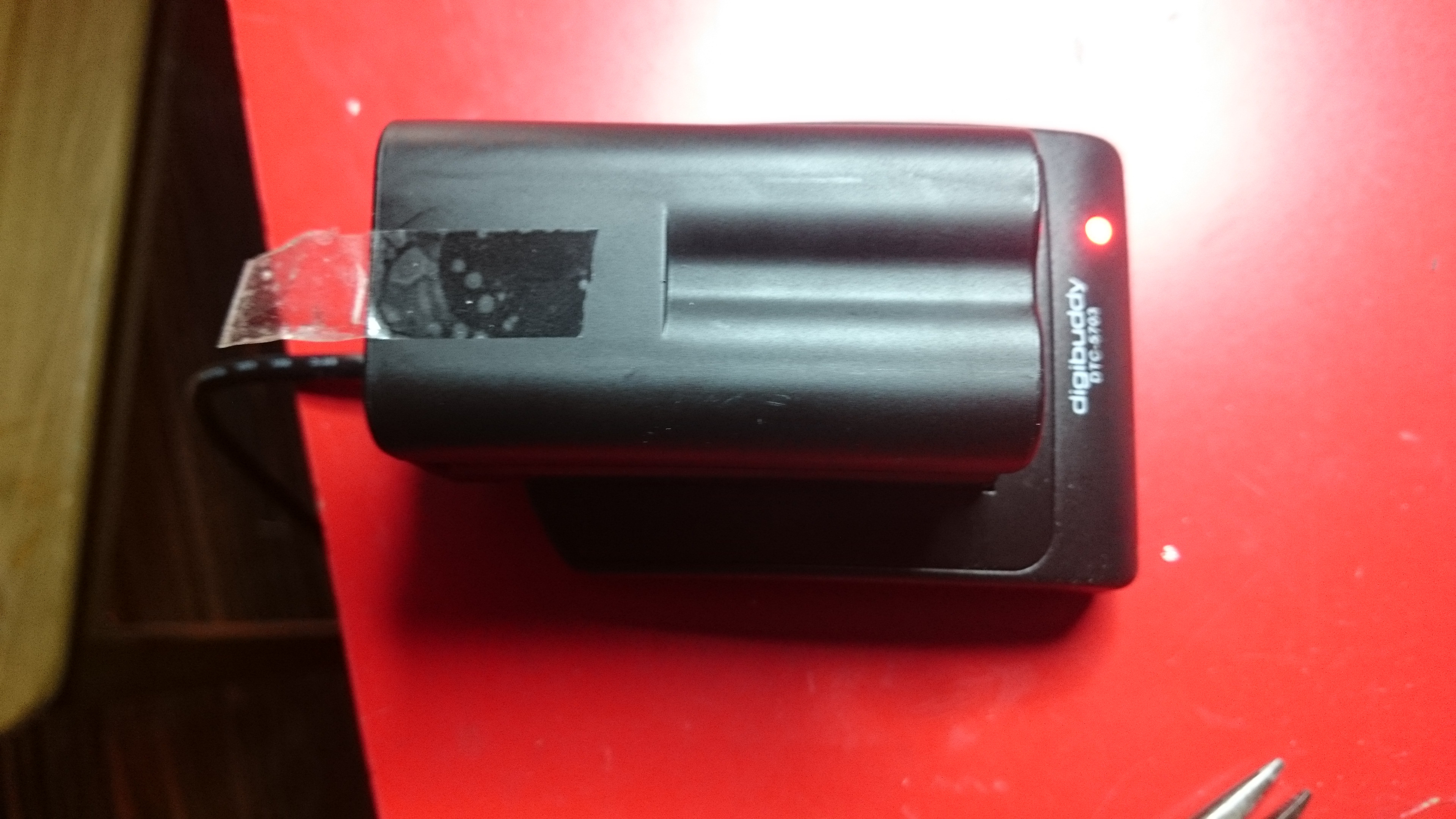
First thing I checked was the battery, which was dead. At 7.4 volts, I had nothing that could charge it but building chargers and batteries gets boring at some point and that point was reached for me :). For 49 euros I got a pirated battery and charger:
I charged the battery and inserted it and a tape in the camera. It sucked in the tape and I recorder a minute.. At this point I wanted to play back what I recorded to see that it was working. I was a bit confused as I could not see any controls such as play, stop, rewind and so forth anywhere :)
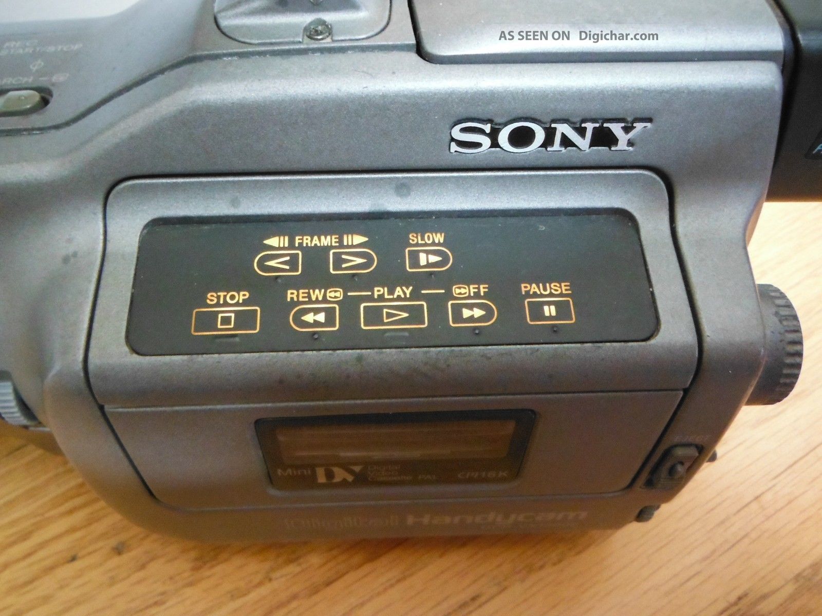
I downloaded the user manual, checked the playback part and tried to follow the instructions. "Press play" was the last step. I could still not see a "Play" button anywhere. I verified that I was reading the right manual, and I was. "What a fuck?!".
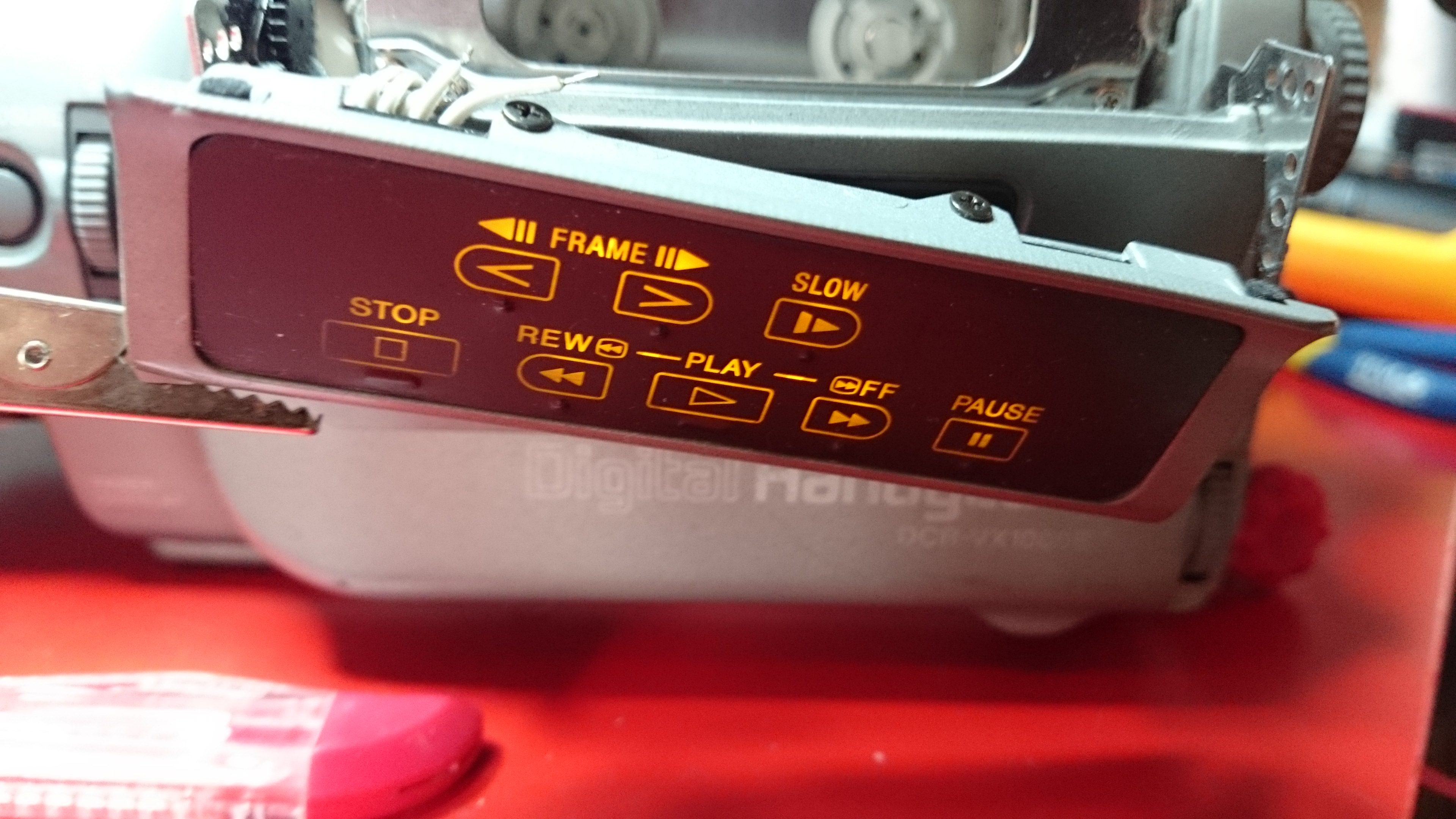
Googling the camera model, they all looked the same to me. Where the hell was the play, rewind and so forth?!! Then I stumbled over this picture:
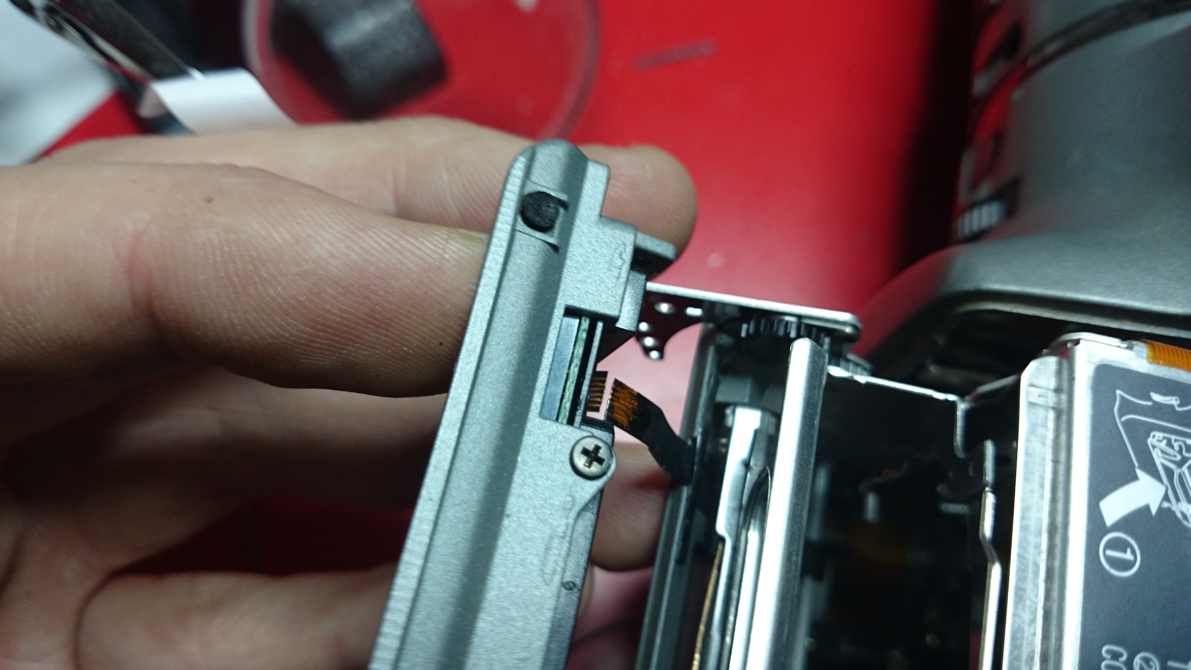
Turns out these are back-lit by leds and can not be seen when the camera is powered off. That's when I discovered this broken flex-ribbon:
This was gonna be tricky.. I had attempted to solder onto flex-ribbons before but always failed miserably. I checked youtube and found this guy in the same situation. His solution was to scrape the plastic off, scrape the copper until it was really shinny, put a tiny amount of tin on the connector and solder on a tiny copper to each missing link. His was missing 4 and he had all the space in the world while mine had 6 and was in the worst thinkable place. Luckily the hatch hiding the tape can be opened while both filming and replaying content allowing me to make a ugly fix to verify that this was the only problem.
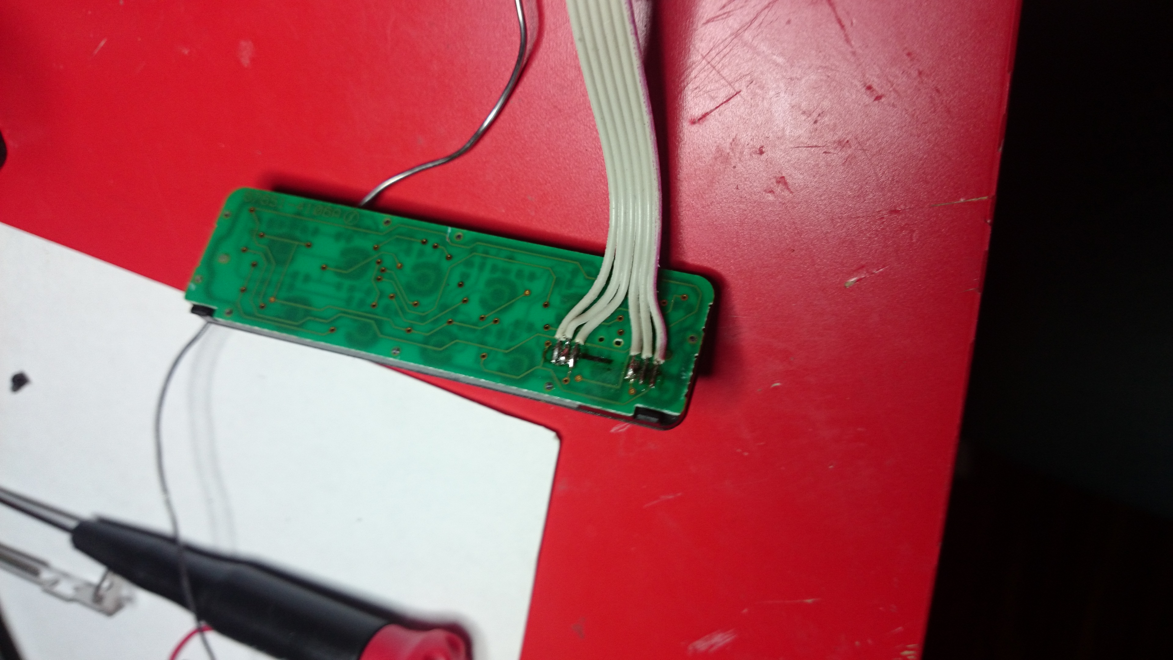
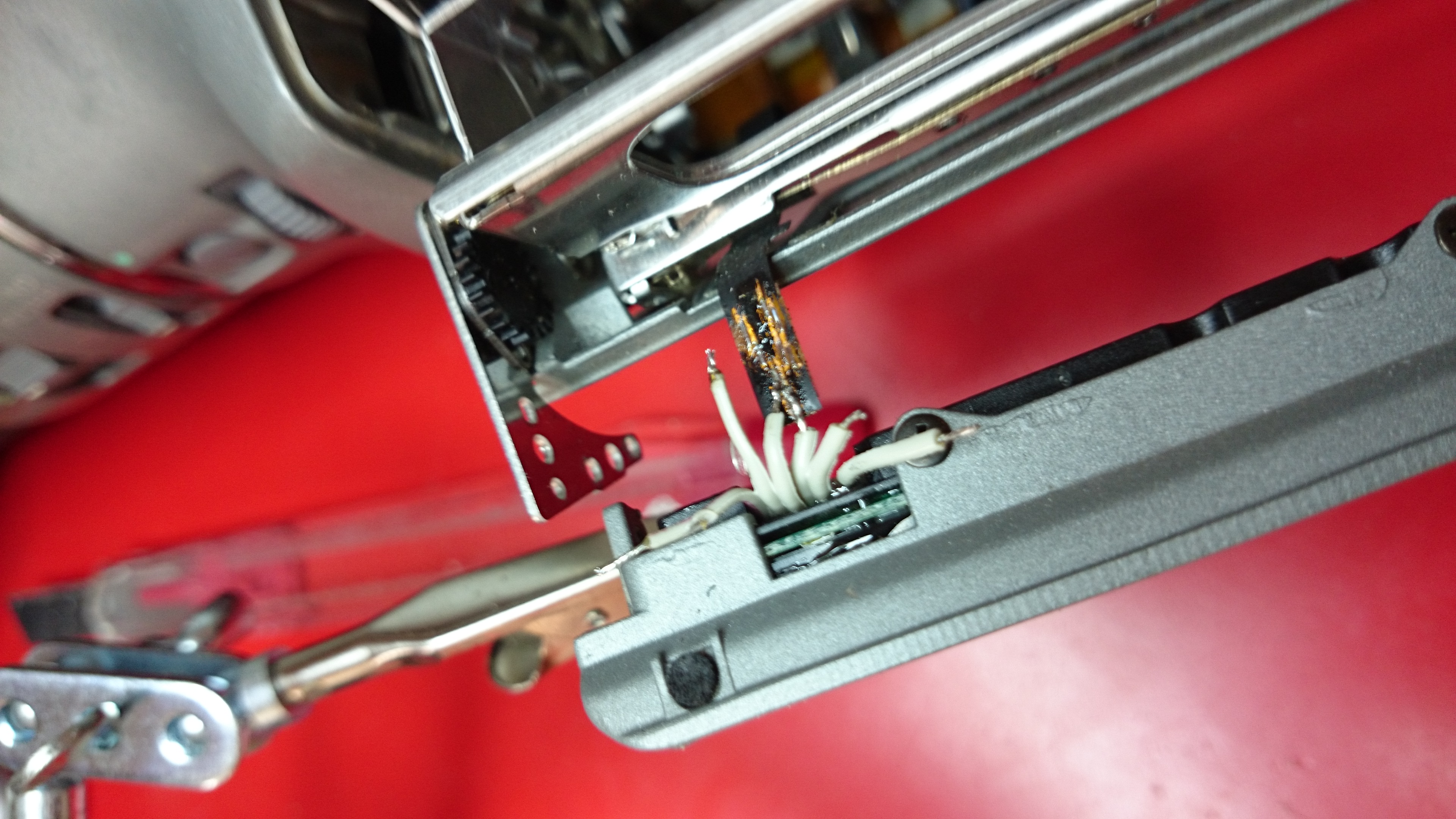
I unscrewed the button panel and cut of 10 plastic pieces that held the controller together and unsoldered the tiny piece of flex-ribbon left on the board. I soldered a flat-cable that I took out of a IDE-cable as a replacement for the broken flex-ribbon. On this side it was quite easy to fit the wiring as there was some space left, once pieces of the plastic was grinded away with a dremel. I resealed the panel with 2 component epoxy-glue and continue to getting ready to attach the other end of these 6 cables.
Like I said, soldering something onto a flex-ribbon is not a simple task and having failed before I refused to start doing this on the camera until I mastered it. Luckily I still had the tiny piece of flex-ribbon left from the control. It was only 8mm long but big enough for me to get some practice. As I felt I had control of it, I moved over and started working on the camera for real. Two down, 4 to go:
By placing the soldering's like a step-stair along the lanes, even these "thick" cables could be connected right on the lanes without short-circuiting any of them. I would lie if I said this was easy and that I did not curse during this whole exhausting 1 hour procedure.
If you are doing something similar and and need to solder on to a flex ribbon my best advise is avoid breathing. Place the replacement wire using a scalpel and once you think you got it where it needs to be, hold your breath and just touch the cable with the solder-iron for a fraction of a second. Make sure you have space around you while working and that cables aren't being tangled up and potentially destroying your work as you lean out. A good magnifying glass is almost a must. Make sure you don't support the weight of any parts on these tiny solder-points as it will rip of and potentially destroy more than you just fixed. Additionally take time to verify that every connector is soldered firm and does not cross-connect to other lanes using a multimeter, before connecting the battery/power.
About half an hour into the process the plus and gnd is connected, allowing the LED's to once more shine:
After all 6 wires are back, I re-mounted the hatch and did a little measurements to verify all was good.
All but one line worked but it didn't take long to find the faulty connection.
Don't let my cats lack of cooperation undermine anything I have just written, she just hates cameras:
I bought a Conceptronic CNETCAM (Embedded linux web-based security camera) some years back. After a burglary in my place it gave me that extra feeling of security to be able to login and see that all was good at home if I ever was worried. It was cheap but lacked a lot in the web-design-department. I figured if I changed the firmware, it could look nicer and run a fullscreen picture instead of the sorry ass borders created by conceptronics. I downloaded the firmware and started to analyzing the binary file using strings and greping for html-tags. I could see html pour past my screen in clear-text, meaning no compression was used on the binary file that constituted the firmware. Great, this simplified the process a lot.
I started by changing the colours around, uploaded the firmware, rebooted the camera and it all worked fine, my colours were applied. "Awesome", I thought.. This will allow me to mod the webpage without extracting and re-compiling a working firmware file as long as my HTML code could fit the same space as the old code used. I did a few more changes but this time uploading it gave a error message indicating that the firmware checksum was wrong.
While trying to find the checksum that must have caused the update error, I looked around the web for people that might have done this before I found almost nothing for this specific camera.
I decided I might get lucky with a google-dork and searched for parts of the html-title, some distinct text on the page where the camera could be viewed and added parts of the url to the document in the query. Bingo! Around 75.000 hits. While looking through the results I fast realized that google removed part of my query, namely "Conceptronic" and 99% of the results had everything my dork demanded but the name of the vendor. Some cameras where D-link DCS-900, some SparkLAN CAS-330 and about 5 other vendors, all using the same basic html-code. But none of them had a tool embedded in their GPL-code which allowed me recompile a new firmware from scratch.
I figured maybe another vendor had the tool so I turned the process around. The camera I bought had a really distinct look. It was thin, wide and long, with a large screw around the lens to adjust focal length. I googled "Ip web camera", choose "Images" and started looking around. I found another 5 vendors with very similar design while going through the hundreds of images in the search, and started mapping them out. As a test I downloaded the Sparklan CAS-330 firmware, uploaded it to my camera, rebooted.... and it just worked. My camera just changed interface to the classical blue sparklan interface, but every function worked. I was surprised because I kind of expected to brick it.
This is where it all took a sharp turn. While playing around with my own camera, flashing it with loads of different firmwares from a heap of other cameras with same appearance, specs and functions I accidentally broke a script I wrote and managed to flash the device with an error. I actually flashed it over and over and just saw a error flashing by the CLI that didn't seem to matter as the camera rebooted and came back again with the changes I made in place. I started debugging the script, found my typo and realized with this bug in place, there was NO WAY it should would have managed to authenticate to the camera, it just firmware flashed without caring who I was.
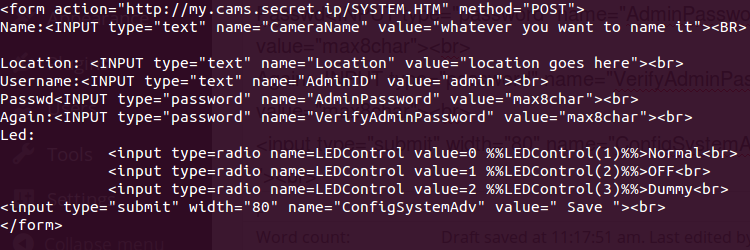
I wrote a simple html document
and loaded it in my webbrowser, and clicked Save. The camera died for a few seconds then prompted me to login again. I entered the same username and password as I just saved. It worked!
I could not believe my eyes. Looking at all possible html documents in the webroot, I realized most of the documents on the embedded webserver was susceptible the same XSS-attack. I could not view many of the html-pages without being authenticated, but I could do a POST-GET and apply new values as long as all input-strings needed were there. I could change the password, flip the image upside down, set the capture resolution and all other functions in the camera.
I started compiling a list of my finds, mostly cameras that looked alike it, had similar paths in the webUI and the size of the firmware. Flashing my own camera over and over with all these different cameras firmware I confirmed that this bug could be found in most of the cameras I suspected had the same initial manufacturer. I turned my eyes back to Conceptronic again. Turns out that Cellvision (a Chinese OEM-vendor, now owned by Sparklan ) made the original code and OEM-sold it to Conceptronic but that tons of other companies also did the same. All of them just branded them with their own logos, without changing anything but the webUI.
I figured I could not be the first to have made this find and it turns out some people had found a XSS exploit on a single make or model, but no-one seem to have understood they were actually all the same camera. I was amazed.
Did I just find a way to get root on 75.000 cameras?
It seems I had. I started realizing how bad this was. 75.000 people had trusted these devices to the extent that they port-forwarded them through their DSL-modem or corporate firewalls, right into the inside of their networks. As this hack actually allowed me to upload a new firmware that seemed to work cross all these cameras, I could have written a firmware that allowed me to nmap their whole infrastructure and display this information to me on the outside. Once I had this information another firmware could route the webserver to an hardcoded internal IP and port, actually granting me access to ANY of their internal services, just like I was in their network. Needless to say this could all be scripted and automated, making the collection of information and routing more or less instantaneous.
At the point of this discovery most of the cameras were at or near their end of life by the vendor, but still actively used by people and companies so I decided to sit on the information rather than sharing it with the world. Today all of the cameras are EOL'ed, but quite a few are still out there. As I don't want to help people abusing this, I will not share the complete list of models and makes but rather say:
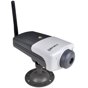
If you have a camera that looks something like this
I strongly suggest you write a html-document like the one above, change the hostname to it's IP (and :port if you don't run it on port 80) and see if it is vulnerable. I would also like to point out that none of the firmware updates available to any of the different camera firmwares I was playing with actually solved this specific issues, and as of today I doubt anyone will.
I recently purchased a new camera for my motorbike. What made the Sony HDR-AS30V stick out, beside all the regular stuff such as full HD on 60 fps, remote control via Android and IOS-devices was that it has a GPS device that stores all data and allows you to overlay this information on the final rendered video. I tried doing this collecting data from a GPS device with decent results, but figured a all-in-one solution was a better deal in the end.
I added a 32 gb micro-SD to be able to record hours of driving but soon noticed some very annoying limitations with the camera. The first one being the internal microphone which picked up more wind than motor noise. The camera has an external microphone-jack, but with the water-proof casing on (which by the way is the ONLY way to mount this camera anywhere), the microphone connector was hidden under the casing, and it's locking mechanism.
The second thing that really annoyed me was that the camera could not be charged while recording, as the camera went in to a USB-mode which disables the recording feature. Not only was the connector hidden under the waterproof case, but even when out of the case the USB overrode all internal functionality. Using a USB test-block I built a while back for sniffing the USB-protocol, I disabled the two middle-pins (data+ and data-) hoping that this workaround would allow the camera to ether charge or run off external power, but the camera insisted USB was connected.
Solving the mic-issue:
I don't really need a waterproof camera so getting a hole through the case that could allow the external mic to be connected was not a great concern to me. Worst case scenario I could always bring a roll of duct-tape to cover the holes if I ever wanted to go diving with it. But as the locking mechanism was just above the jacket, I had to substitute this with some form of lock. Not to waste to much time on this, I removed the lock and replaced it with a rubber-band. To see the difference between a external vs. internal microphone I cut this clip together:
Sorting out the power issue:
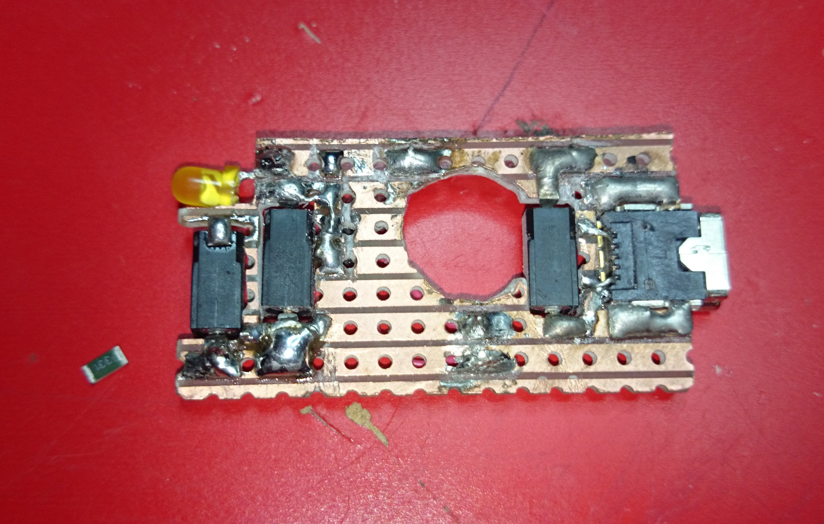
As for the charging part I figured I would build a tiny lithium-ion charger that could fit somewhere in or on the camera. With a camera that measuring 6.5cm x 4cm x 2cm which is jam packed with electronics already I decided the circuitboard needed to be housed in a tiny space between the camera and the casing, on the front of the camera as this would be the only place it fitted. Using a dremel I removed enough of the plastic casing to make it fit. Only problem was, this was also where the external microphone cable was connected. Looking around the net I stumbled over the MCP73831T charger circuit. The smallest package I could find was the SOT23-5 measuring about 2mm x 1mm. Since it was just 3 euros I figured I get a few. Things this size tends to get lost never to be found again. After building a few prototypes the first one went toast in just a second, while the second one seemed to indicate that things were working. Measuring voltage however gave very weird results I still to this day can not explain so I started looking for another charging circuit. After a little googling around I found the MAX1555 also contained in a SOT23-5 encapsulation, however this demanded less surrounding components and became the semiconductor I decided to go with in the end.
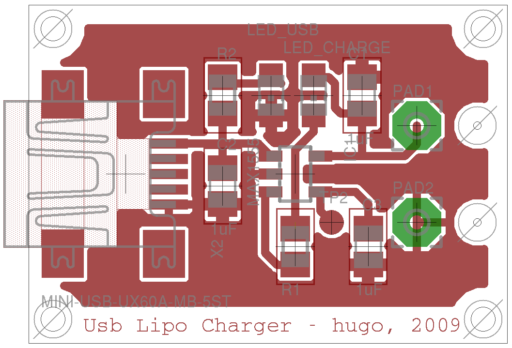
I started learning the PCB (open source software for circuit-board manufacturing) but for some reason all circuits I made and all example circuits I opened was giving me an vague error about not all objects being defined. Since my use-case worked fine with the typical application-setup and I took the chicken-shit way out of this. Learning PCB still remains high on my to-do-list. Like most other things in this world, I was not the first to attempt something similar, and looking around further I found this drawing (credit to Hugo for his great work):
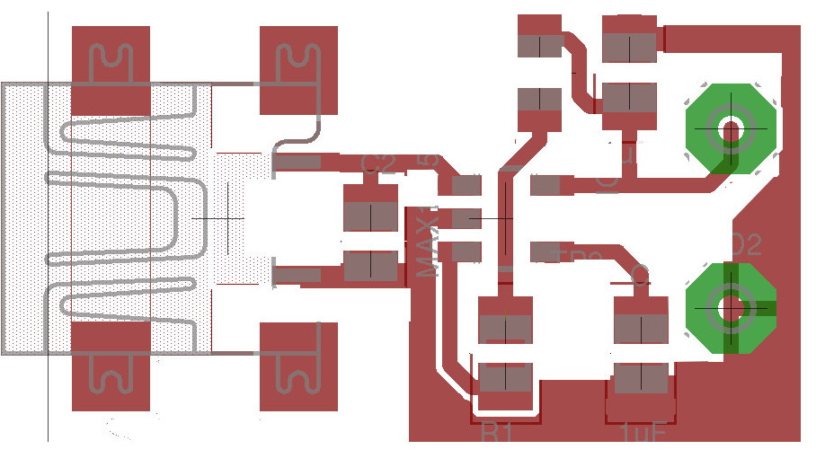
This little bugger might look tiny with a mini-usb covering 1/8th of the board, but fitting it into the Sony HDR-AS30V as was would be like trying to fit a loaf of bread through a key-hole. In lack of better PCB knowledge I loaded it up in Gimp and started removing stuff I didn't need. I didn't see any reason to include the USB-power LED, so this could go, and so could the resistor in front of it, all the screw-holes and unnecessary GND copper surrounding the board, resulting in this design:
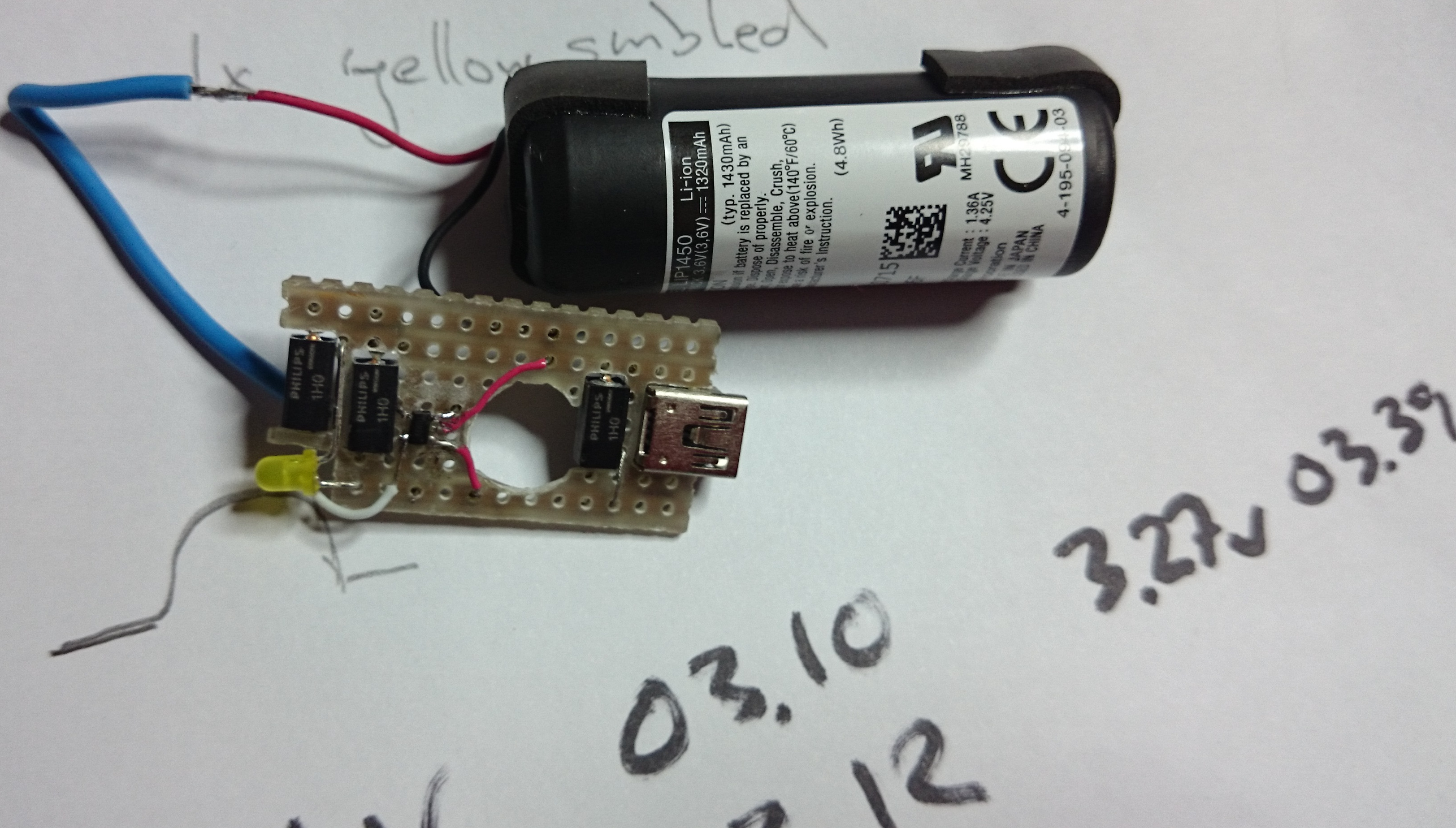
If I would have printed this as is, it would never fit the camera either. It needed a 10mm hole in the middle so the microphone-jack was still reachable, and even my SMB-mounted 1uF capacitors measured 1/3 of the size of the USB connector, and on my tiny board I needed 3 of them. Saying I had a space issue was just the start of it, but I would not let this deter me. The caps had to be inserted into the board to fit. It does not look nice, but it works so don't start hating on me now :) The tiny 330 Ohm smb-resistor to the left of the board was the next component to be added.
Next component to go on is the tiny MAX1555 SOT25-5. Measuring a tiny 1×2 mm, this component needed to have all 5 legs soldered, a task that took "some" fiddling around before getting it all in place. As this board only has copper on one side, all legs are actually soldered to tiny cables fed through and around the board to connect it with the backside of the board. At this point it was a few hours after midnight and I wanted to finish it up, so not many pictures are taken of the MAX1555, but you can see it pretty okay in this shot taken during the initial charge tests. The battery in was just soldered there for the load-tests, and yes.. This did happen around 03.40am. Sorry about the late night Dremeling, neighbours.
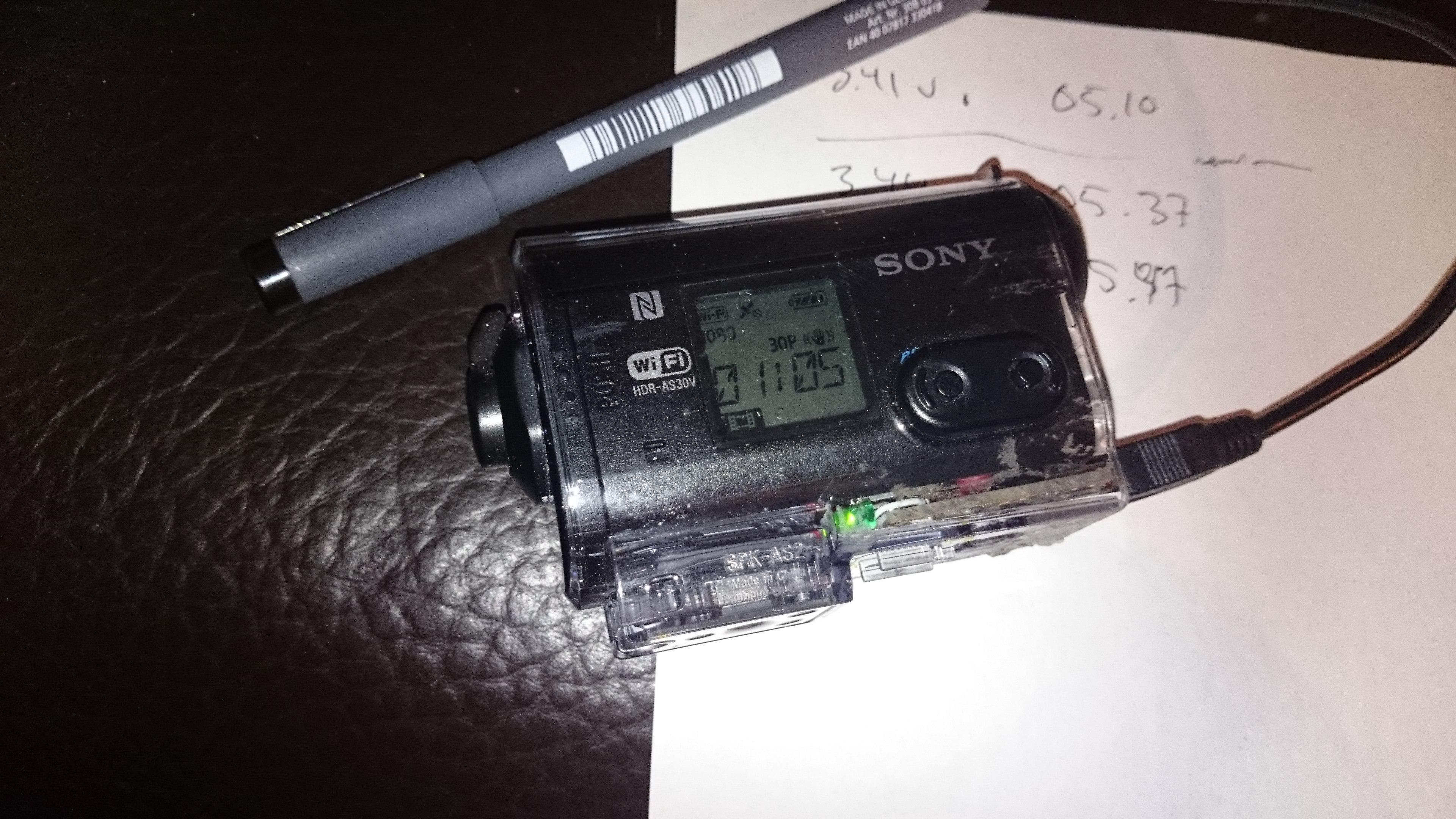
After making sure it all worked, and fitted the waterproof casing I used a 2 component epoxy to add the module to my Sony camera. I also switched the yellow LED to a green one, just for the look of it.
Late this morning I made a test-recording, and for the first time made an 1.5 hour recording in Full-HD without consuming the battery, making this camera the first Sony HDR-AS30V that can record more than 1 hour. Beside mixing up a batch of polyester that I will submerge the whole circuit-board into to make sure it becomes as rugged as the rest of the camera, not much remains to be done to this projects.
Conclusions:
This was a funny hack that only cost a few euro's but added the features that I did not want to be without. The fact that Sony could have saved me these hours spent by incorporating this feature themselves kind of annoys me. Why Sony allowed the camera to be able to create way longer videos, when there was no way of recording over an hour I guess I will never know. Needless to say this was a good day with another warranty voided. :)
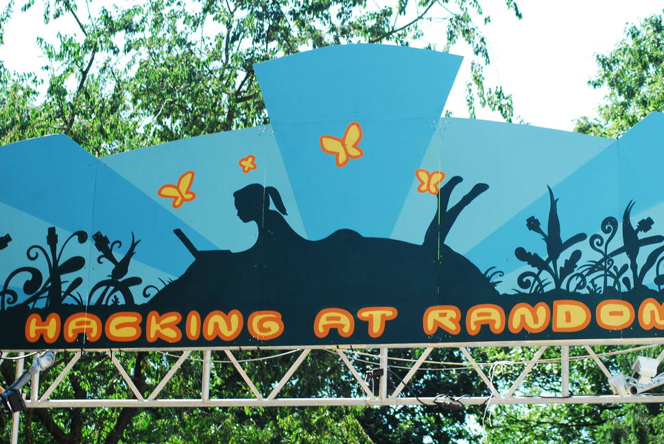
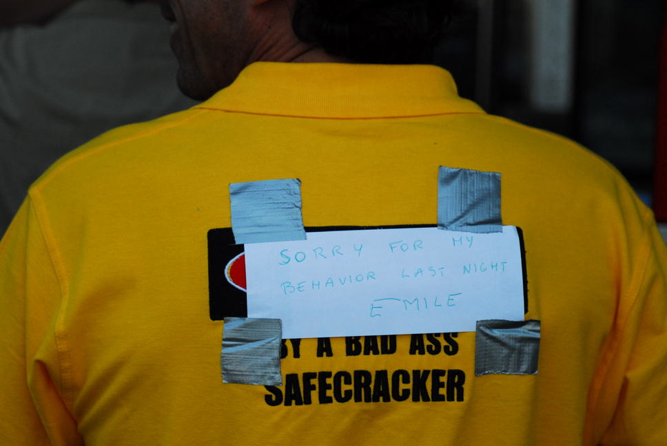
Hacking At RandomAugust 13 to August 16, 2009 It was situated on a large camp-site near the small town Vierhouten in the Netherlands called the Paasheuvel Met Julian Assange who was there to present Wikileaks
Back in 1997 while living in Lund, Sweden I started getting
interested in making music. I had a modest studio with a sampler, a computer and a few friends
who borrowed me synths I could play with. I never produced any music worth listening to, and
late sessions with the sequencer often turned to playing other people’s tracks. I got
turntables and a mixer and started djing in my bedroom. I started out playing progressive trance
and drifted further out over the years, until I was a full-on psy-trance DJ.
I asked a few organisers if I could play at their parties, but I was unknown and no one really
wanted to book me. So me and a few friends started making illegal parties at random locations and
nightclubs who would allow it. Back in these days in Sweden electronic music was a hard sell.
Police connected it with drugs and raided and shut down clubs left and right.
The struggle paid off and I slowly started making a name for myself. I reached out to a few
agencies, but none were interested in representing me. It didn’t bother me, but what did
was their lack of feedback. I could do this better.
Some guy on IRC said he had a killer domain spare. intelligens.nu, registered
1 December 1999. I will not share his name as I am not sure how legally it was purchased.
For a few months it was one page with my own photo on it and a link that said click on the
picture to enter the site. Biography, contact info, a couple of MP3 demos, booking info. An
agency of one, representing the one artist nobody wanted.
The picture you clicked to enter. From my own backup — the Wayback capture of this page saved the HTML but not the image.
Then a friend (Dj Wiking) asked if he could have a profile too. He had been a huge influence and supporter, and one of the people
who I made events with, so needless to say I accepted him.
It got away from me
By April 2001 there were fourteen acts. By early 2004 the list had a hundred names on it,
across Sweden, Denmark, Norway and Finland. Somewhere in there it stopped being my page and became a thing people applied to join.
April 2001, three months later. Fourteen.
The party calendar ended up with 1,012 parties in it. Not mine —
everyone’s. Any member could post their own event. 373 different organisers, 316 venues.
That is the whole arc in five numbers. 2002 was the year it worked. By 2004 it was thirteen
parties and a lot of silence.
The thing I am still proud of
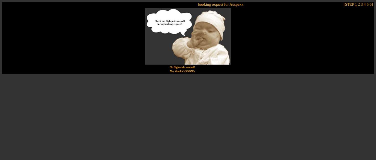
If you booked an artist through STP and that artist lived somewhere else, the site went and
found out what the flight would cost. Origin airport, dates, and it scraped a travel site for the
fare and the airline and showed you the real number.
There was no API. It fetched the page, found the price,
stripped the rubbish out and split what was left into strings. I loaded 1,915 IATA codes into a
table so it knew what airports were.
Step one of six.
I have never come across anyone else doing that, then or since. I am sure someone did —
I just never saw it, and as far as I can tell nobody is doing it now either.
No cut
Everyone was hosted free and every deal was non-exclusive. If a label or an agency wanted one
of my artists, that was between them and the artist. I did not take a percentage and I did not ask
to be told.
The only money that ever moved was sideways — I did deals with equipment suppliers so
people on the roster got about 20% off. And of course to keep the domain registered.
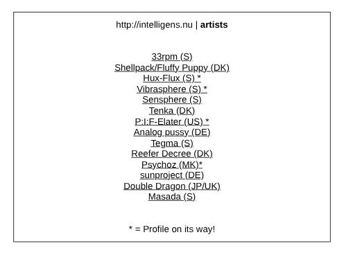
The roster, grouped by country.
How it was actually built
This whole monster was coded in notepad on Windows 95, then WinSCP. Straight onto the live server while people were using it.
There was no version control, no staging, no local copy. What there was instead, in the
backup, is this:
That is the rollback plan. Copy the file, break the original, copy it back if it screams. Two
saves in two days while I was building the flight scraper, which tells you roughly how well that
was going.
27% of the files were last touched between ten at night and six in the morning. The busiest
month in the entire archive is January 2004, which is the month the flight thing got written.
The server that went to Germany
A friend worked at Song Networks and had a box racked there. It hosted a lot of domains —
mine was one of many, and he ran it for years without anyone minding. Then their security
people took exception to something on one of his other domains, traced it back to the
machine, and took it.
He lost his job over it. He did get the server back eventually, and he got me my data, and I
moved the hosting somewhere else. The logs tell the rest: statistics stop on 25 December 2003 and do not resume
until 18 April 2004. Traffic never recovered — 4,520 visits in May 2003, 346 in April 2004.
When I left Sweden the current server got left there to collect dust in a basement. The friend keeping it moved to Germany and took it with him. Years later he
asked if I wanted it back, and I said the machine was rubbish, just save the disks.
He did. Those disks are why some of this still exists.
STPv3 is on its way
There is a file in the backup dated 15 September 2005. It is a placeholder page with an
ASCII-art picture on it and a title that reads STPv3 is on its way.
15 September 2005. This is the entire v3.
I have no memory of this whatsoever. There is no v3 code anywhere. I announced it a few weeks
before I left the country and never wrote a line of it.
The grave
On 31 December 2008 I sent an email to everyone who had ever been on the roster.
The web-hotel a friend had been running was closing, usage was down to twenty people a week,
and I was tired of saying well next year I’ll follow up on it. Nine years, five
servers, four redesigns. HTML to PHP3 to PHP4 to PHP5. Flat text files to MySQL.
Coda
I got the databases running again this week, on a laptop, in a decade none of that code was
written for. It took a compatibility shim, a TYPE=MyISAM search and replace, and
turning off strict mode because somebody entered a party on the 31st of September 2000.
It all still works. The flags load, the roster is grouped by country, and the booking form still
asks you about flight prices next to that baby.
Somewhere in a box of old hard drives is a zip archive called JONAS.ZIP, and
inside it a folder of .BAS files I apparently wrote in the summer of 1996, signed
911^aNGEL! of X-fUSiON!. Opening one in a text editor gets you a wall of binary garbage
— QuickBASIC saved programs in a tokenised format unless you explicitly chose “save as
text”, and sixteen-year-old me never did.
The fix was sitting right next to the problem: another archive in the same folder held QuickBASIC
4.5 itself. Loading a tokenised .BAS file in the real IDE detokenises it back to readable
source automatically — that’s the whole trick. So: DOSBox, a mounted drive holding
QB.EXE next to the recovered sources, and thirty seconds of ClamAV first out of habit before running
anything this old. It came back clean, aside from flagging Microsoft’s own compiler and linker
as “packed” — which they are, with Microsoft’s own EXEPACK, a false alarm as old
as the files themselves.
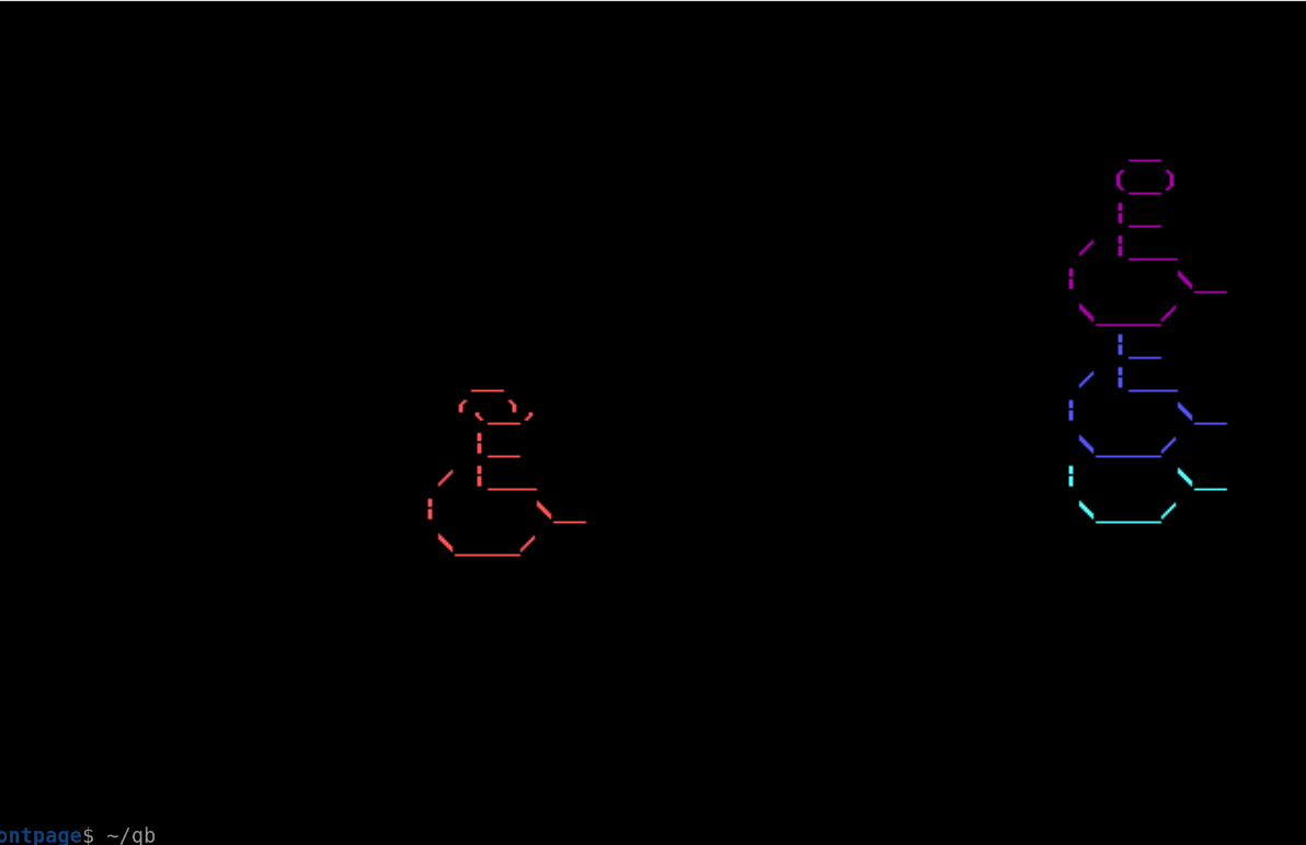
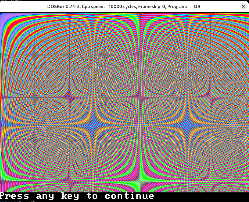
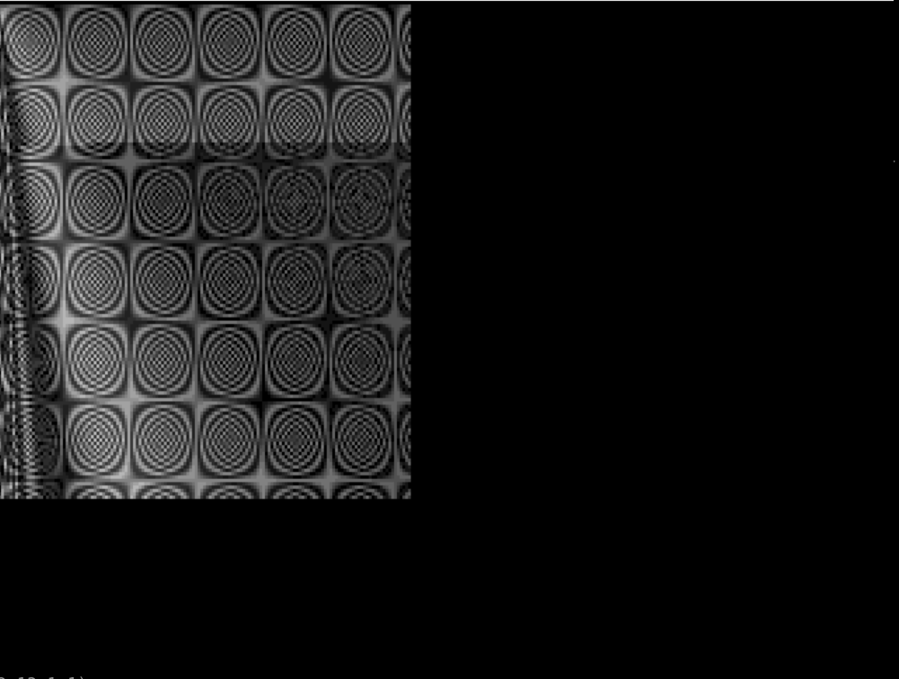
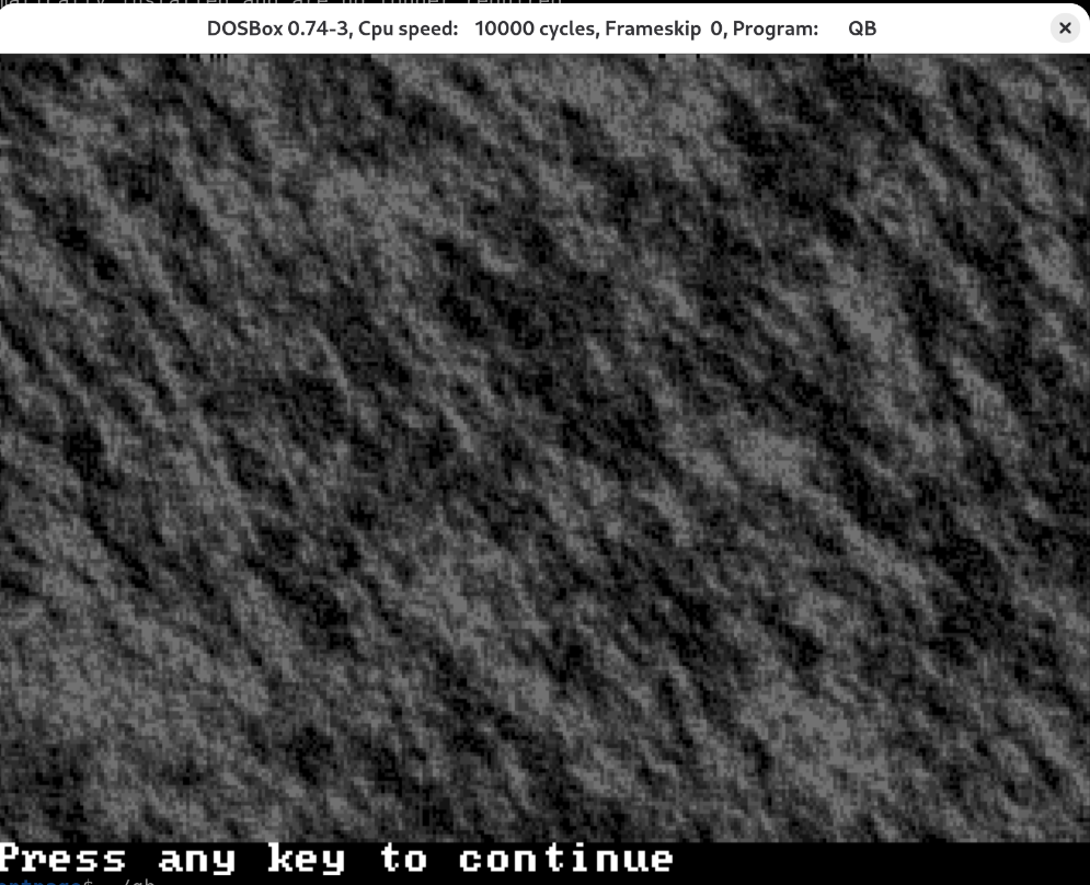
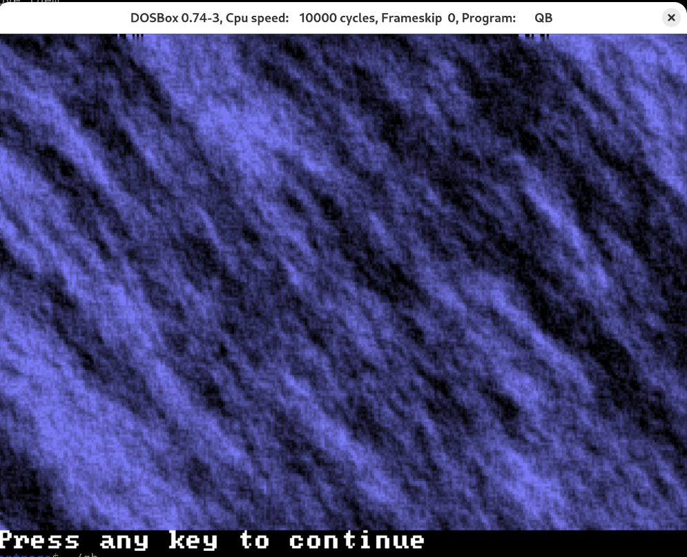
Most of what's in there are palette and pixel-plotting experiments: a bouncing logo, a couple of
sine/cosine plotters, some rock and marble texture generators, and a keftail fractal (not sure where
this name comes from, or if it had a different name back then). The dated files in the folder span
the end of June to the middle of August 1996, so call this the middle of that.